

Control valve and diaphragm for use in the control valve
a control valve and diaphragm technology, applied in the direction of diaphragm valves, engine diaphragms, machines/engines, etc., can solve the problems of reducing durability, affecting the service life of parts, and easy damage to the diaphragm
- Summary
- Abstract
- Description
- Claims
- Application Information
AI Technical Summary
Problems solved by technology
Method used
Image

Examples
first embodiment
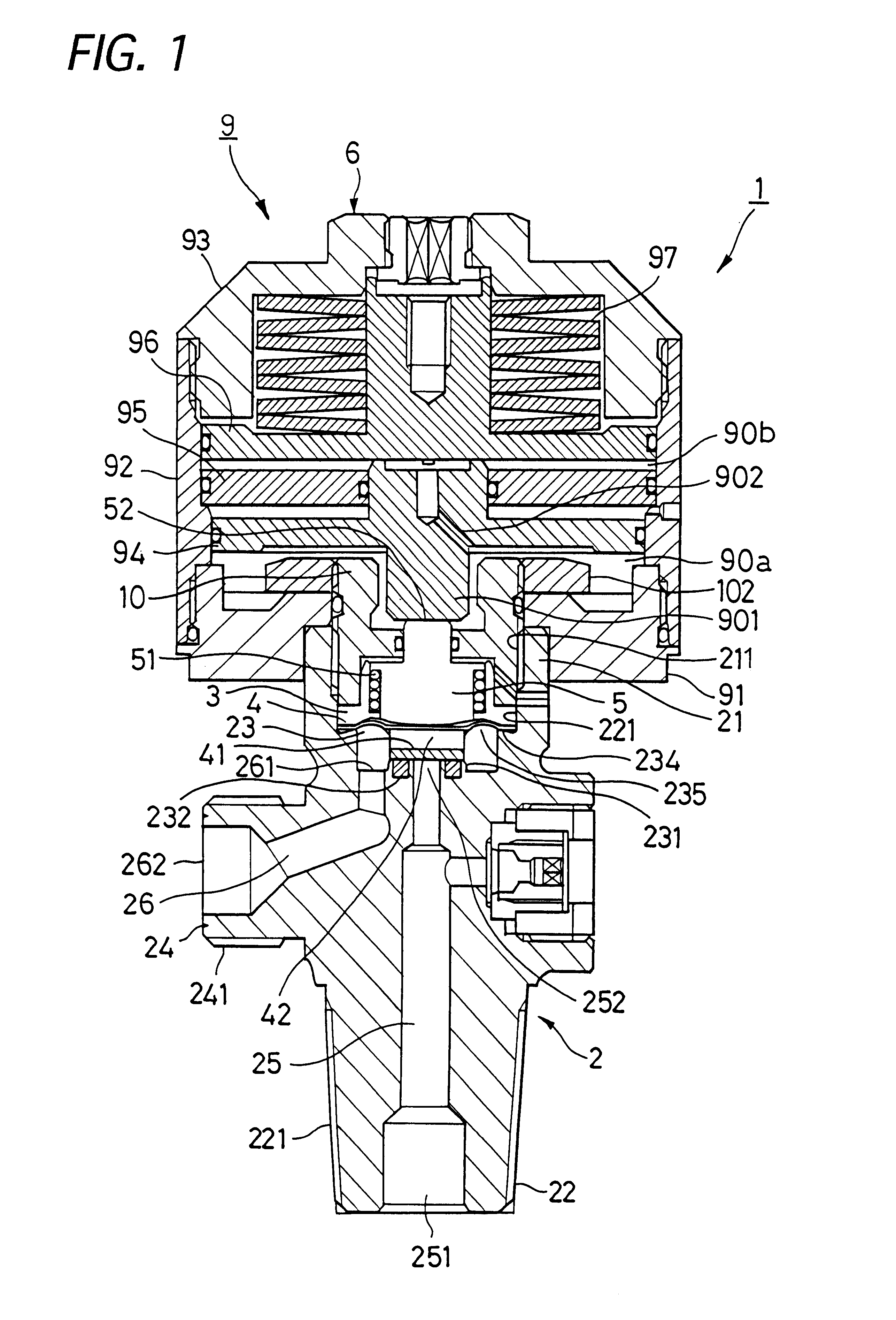
the control valve according to the present invention will be explained below, referring the attached drawings. A control valve 1 according to the first embodiment comprises a valve body 2, a clamping member 3, which is stored in a cylindrical portion 21 of the valve body 2, a diaphragm 4, a valve controlling member 5 which is inserted into a center portion of said clamping member 3, and a controlling member 9 for controlling said valve controlling member 5 in an advance or retreat direction. In this embodiment, the controlling member 9 is realized by an air actuator.
The valve body 2 has substantially a cylindrical shape, which comprises a fixing portion 22 provided at a lower portion thereof, a valve chamber 23 which has a valve seat 231, a cylindrical portion 21, which has an inner side air space 211 being connected to said valve chamber 23, a connecting portion 24 having a gas outlet 262 at a top end portion thereof, a gas current in path 25 through which a gas comes in, and a gas...
second embodiment
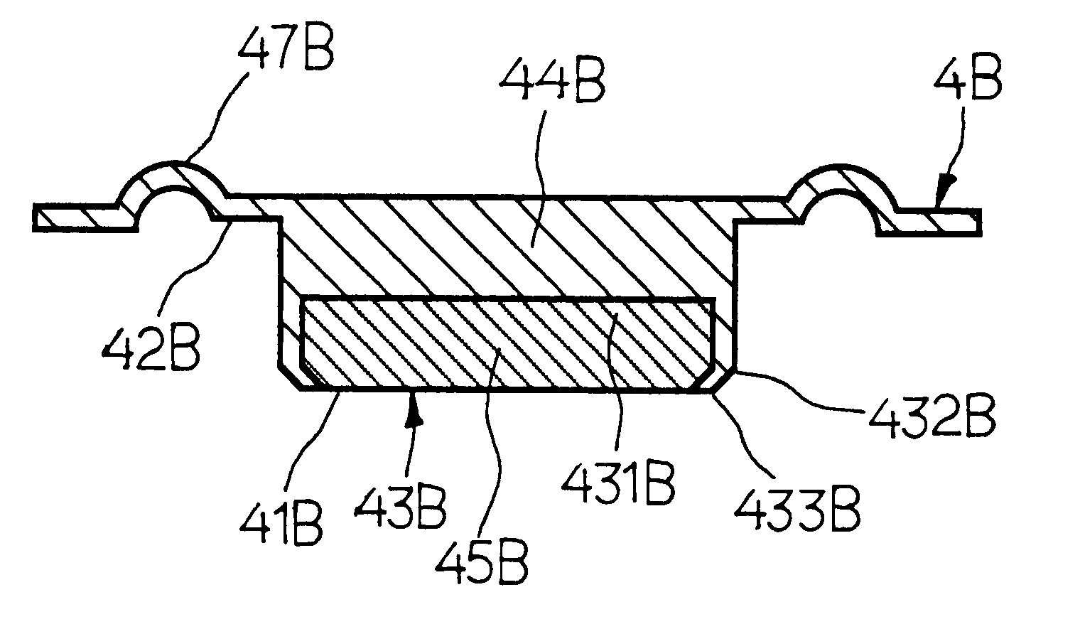
Such an urging member 41A is bonded to a pressure-member 47 made of metal by the above mentioned method. In the pressure member 47, is provided a bolt portion in the center of the surface, opposite to the surface where the urging member 41A is bonded. The bolt portion 471 penetrates through the hole 40 formed in the center portion of the diaphragm 4; the diaphragm 4 is fixed to the bottom of the bolt portion 471 by means of welding in an airtight manner. To a male thread 472 formed on the bolt portion 471, fits a female thread 481 of a connecting member 48. The top end portion 481 of the connecting member 48 is urged against the surface of the diaphragm 4 so that the diaphragm 4 is held and fixed between the connecting member 48 and the urging member 47 in an airtight manner. On the bottom end portion of the connecting member 48, a groove 482 is formed in a circumference direction. To this groove 482, a controlling means such as an air actuator and a manual type switching device is ...
PUM
 Abstract
Description
Claims
Application Information