Child safety slide door apparatus for vehicles

a technology for sliding doors and children, applied in the direction of passenger lock actuation, door, lock applications, etc., can solve the problem of not being able to achieve the maximum utilization of the drive devi

Inactive Publication Date: 2004-03-09
AISIN SEIKI KK
View PDF34 Cites 60 Cited by
  • Summary
  • Abstract
  • Description
  • Claims
  • Application Information

AI Technical Summary

Problems solved by technology

However, the drive device is initiated subject to a predetermined displacement of the slide door, requiring that the slide door must be manually displaced through the distance.
Thus, maximum utilization of the drive device cannot be achieved.

Method used


Image

  • Child safety slide door apparatus for vehicles
  • Child safety slide door apparatus for vehicles
  • Child safety slide door apparatus for vehicles

Examples


Embodiment Construction

Preferred embodiment of the present invention will be described hereinafter in detail with reference to the accompanying drawings.

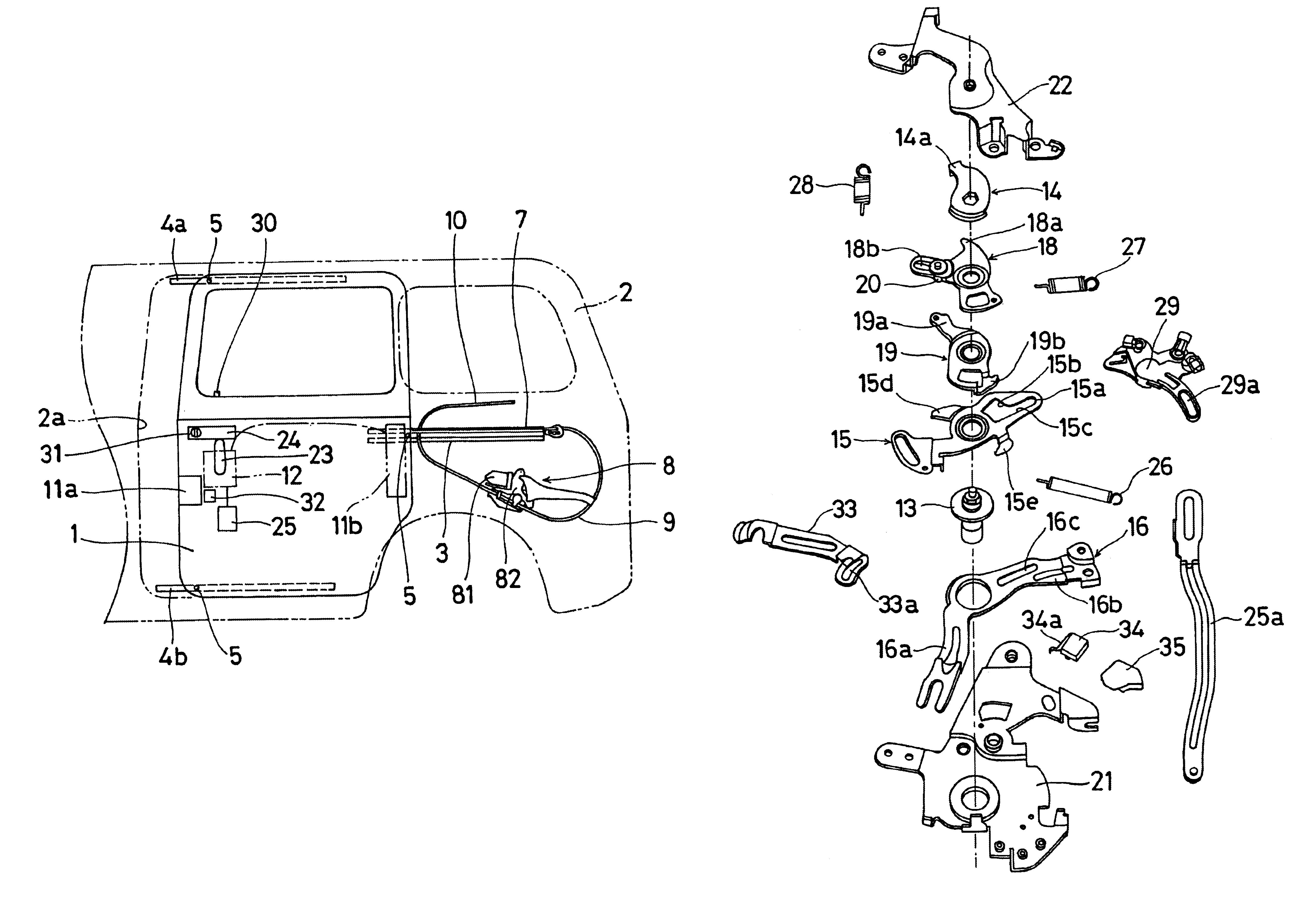
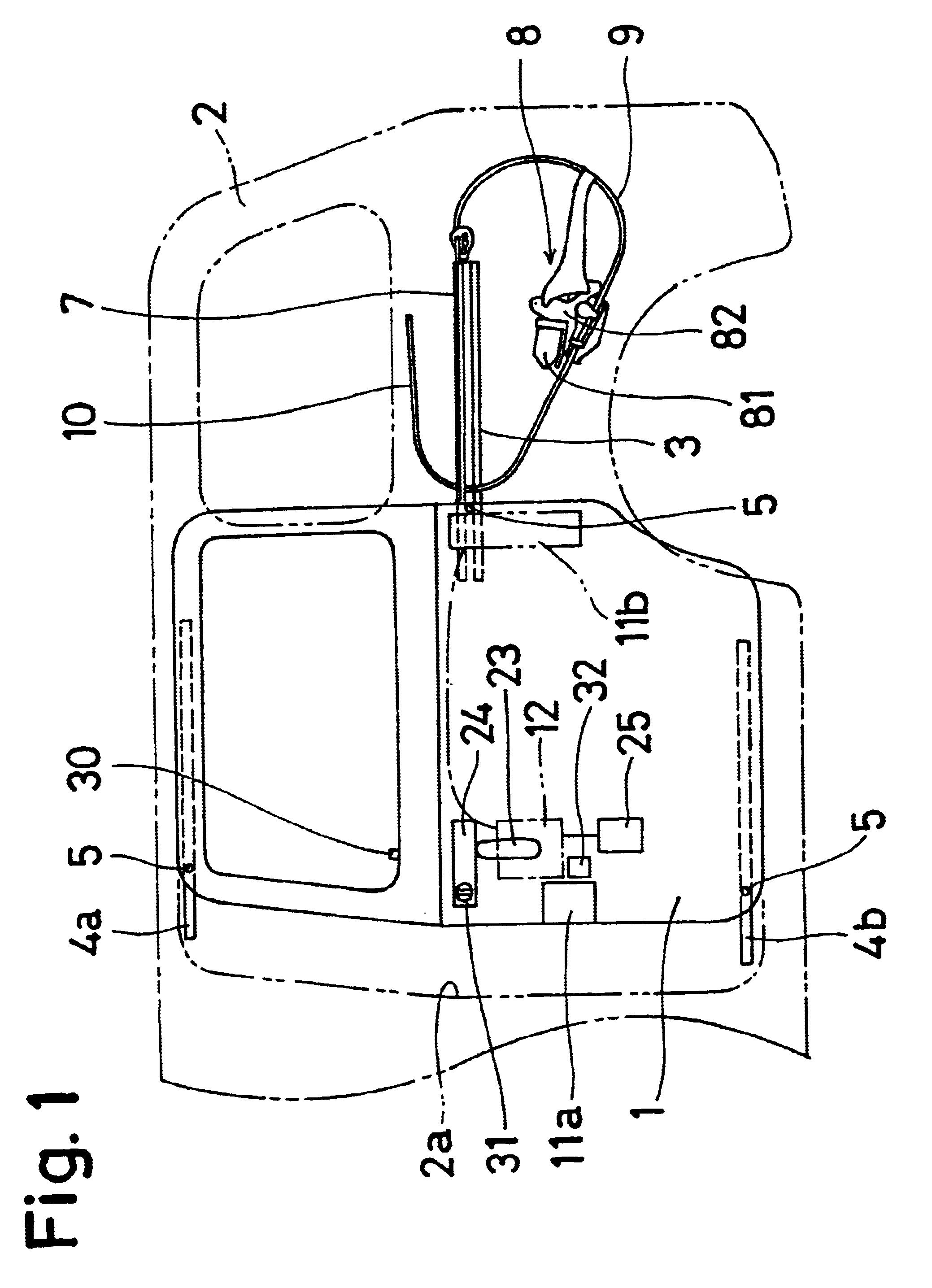
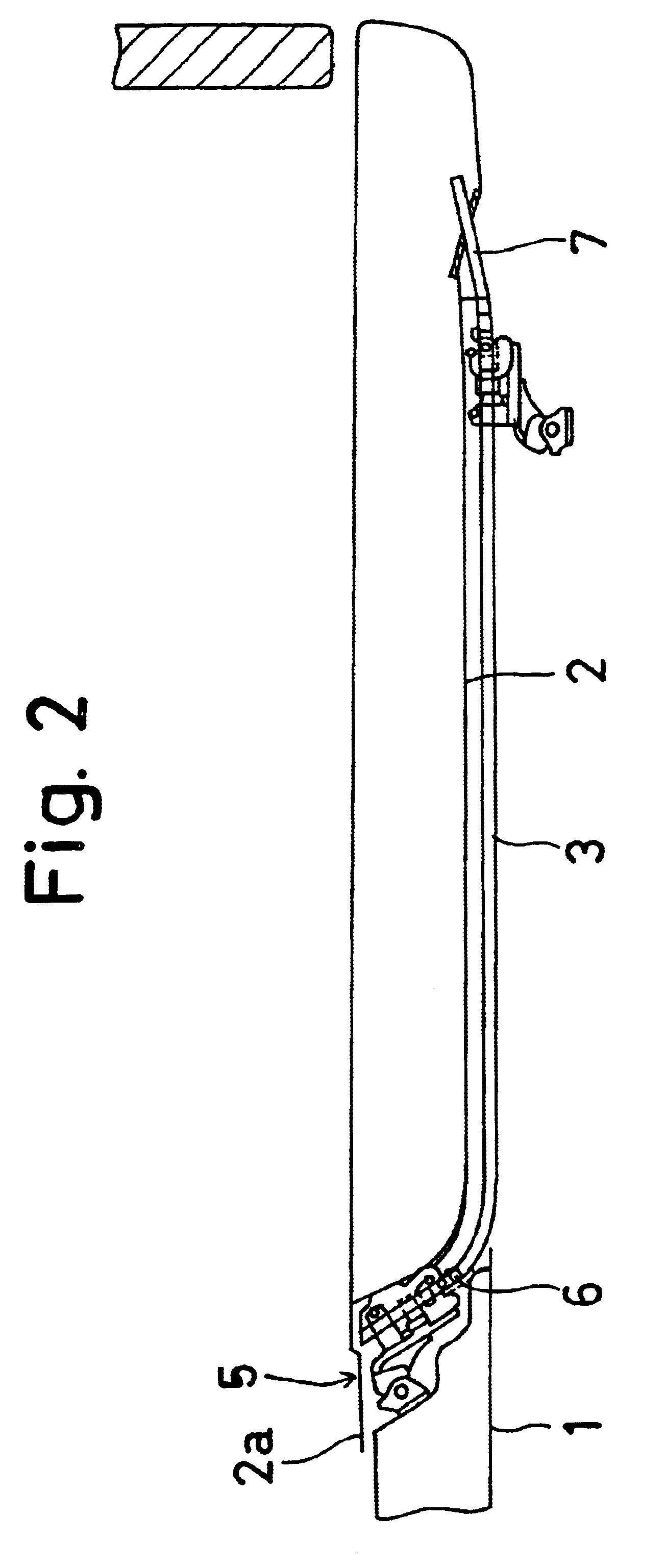
First of all, with reference to FIGS. 1 and 2, there is illustrated a rear portion of a vehicle body of a van type vehicle. The vehicle body is formed at its lateral side body 2 with an opening area 2a which is configured into a substantially rectangular shape. The opening area 2a is closed and opened by a slide door 1 which is supported by an upper guide rail 4a, a lower guide rail 4b, and a center guide rail 3 so as to be movable in the vehicle lengthwise direction which corresponds to right-and-left direction in FIG. 1.

The upper guide rail 4a is arranged along an upper periphery of the opening area 2a so as to be close thereto and is secured to the lateral side of the vehicle body 2 by means of suitable connecting devices such as screws (not shown), while the lower guide rail 4b is arranged along a lower periphery of the opening area 2a so as to be clo...


PUM


Abstract

A vehicular slide door apparatus includes a movable slide door, inside and outside door handles operable to initiate opening and closing movement of the door, a drive device that assists the slide door movement, and a remote control device that includes a door lock device and a switch. An open lever is operatively associated with the inside door handle to transmit operation of the inside door handle to the lock device, and a child-proof lever is operable to prevent operation of the inside door handle from being transmitted to the open lever. The switch is engageable by the open lever and is operatively associated with the drive device such that operation of the inside door handle produces selective actuation and non-actuation of the switch depending upon the position of the child-proof lever, with the actuation of the switch effecting driving operation of the drive device.

Description

This application is based on and claims priority under 35 U.S.C. .sctn.119 with respect to Japanese Application No. 10(1998)-365333 filed on Dec. 22, 1998, the entire content of which is incorporated herein by reference.1. Field of the InventionThe present invention relates to a slide door apparatus for vehicles.2. Prior ArtA conventional slide door apparatus is disclosed, for example, in Japanese Patent Laid-open Print No. Hei. 10-280806.In this slide door apparatus, a slide door, which opens and closes an opening area formed in a lateral side body of a vehicle body, is associated with an electrically operated drive device for facilitating such opening and closing operations of the slide door.However, the drive device is initiated subject to a predetermined displacement of the slide door, requiring that the slide door must be manually displaced through the distance. Thus, maximum utilization of the drive device cannot be achieved.Accordingly, a need exists for a slide door apparatu...

Claims


Application Information

Patent Timeline
Patent Type & Authority Patents(United States)
IPC IPC(8): E05F15/20E05F15/14E05B65/20E05B65/12E05B65/08B60J5/06E05F15/632
CPCE05B77/26E05F15/70E05B83/40E05F15/40E05F15/646E05F15/695E05B81/20E05Y2201/216E05Y2201/22E05Y2201/244E05Y2201/246E05Y2201/434E05Y2201/462E05Y2900/531E05Y2400/854E05Y2800/426E05Y2800/113E05Y2400/856E05Y2900/50E05Y2900/55Y10T292/564
Inventor FUKUMOTO, RYOICHIYAMADA, KATSUHISAOHHASHI, MASAOSUZUKI, SHINTARO
Owner AISIN SEIKI KK
Why Eureka
Try Eureka