Load storage equipment

a technology for storage equipment and equipment, applied in the field of loading storage equipment, can solve the problems of difficult equipment to have large fixed racks, and the inability to expand the fixed racks,

Inactive Publication Date: 2004-04-20
DAIFUKU CO LTD
View PDF4 Cites 338 Cited by
  • Summary
  • Abstract
  • Description
  • Claims
  • Application Information

AI Technical Summary

Benefits of technology

As stated above, the single transferrer can load and unload both the rotary and fixed racks. Differently from the prior art, the carrier of the transferrer does not travel along the fixed rack, but turns and moves vertically. Accordingly, the carrier does not require a large space to travel. The carrier is important in loading and unloading the rotary rack. The fixed rack may be positioned in a space around the transferrer. By making the carrier rotatable on the second vertical axis, it is possible to load and unload the fixed rack by means of the transferrer. Because the transferrer does not need to travel, the carrier can move downward near the floor so that the rotary and fixed racks may include additional stages of turning and fixed load supports respectively near the floor to store more loads. Because the inlet-outlet port overlaps with one of the rotary and fixed racks in plan view, there is no need for an exclusive space in plan view for the port.
The rotary and fixed racks and the transferrer may be positioned in a storage chamber defined in a housing. Loads can be carried through the inlet-outlet port between the storage chamber and a clean room outside the chamber. The storage chamber can effectively store the loads carried from the clean room.

Problems solved by technology

If the storage equipment is installed in a room or house small in scale or size, however, the fixed racks cannot be enlarged.
For example, if the storage equipment is installed in a special room such as a clean room, which is limited in size, it is not easy for the equipment to have large fixed racks.

Method used


Image

  • Load storage equipment
  • Load storage equipment
  • Load storage equipment

Examples


first embodiment

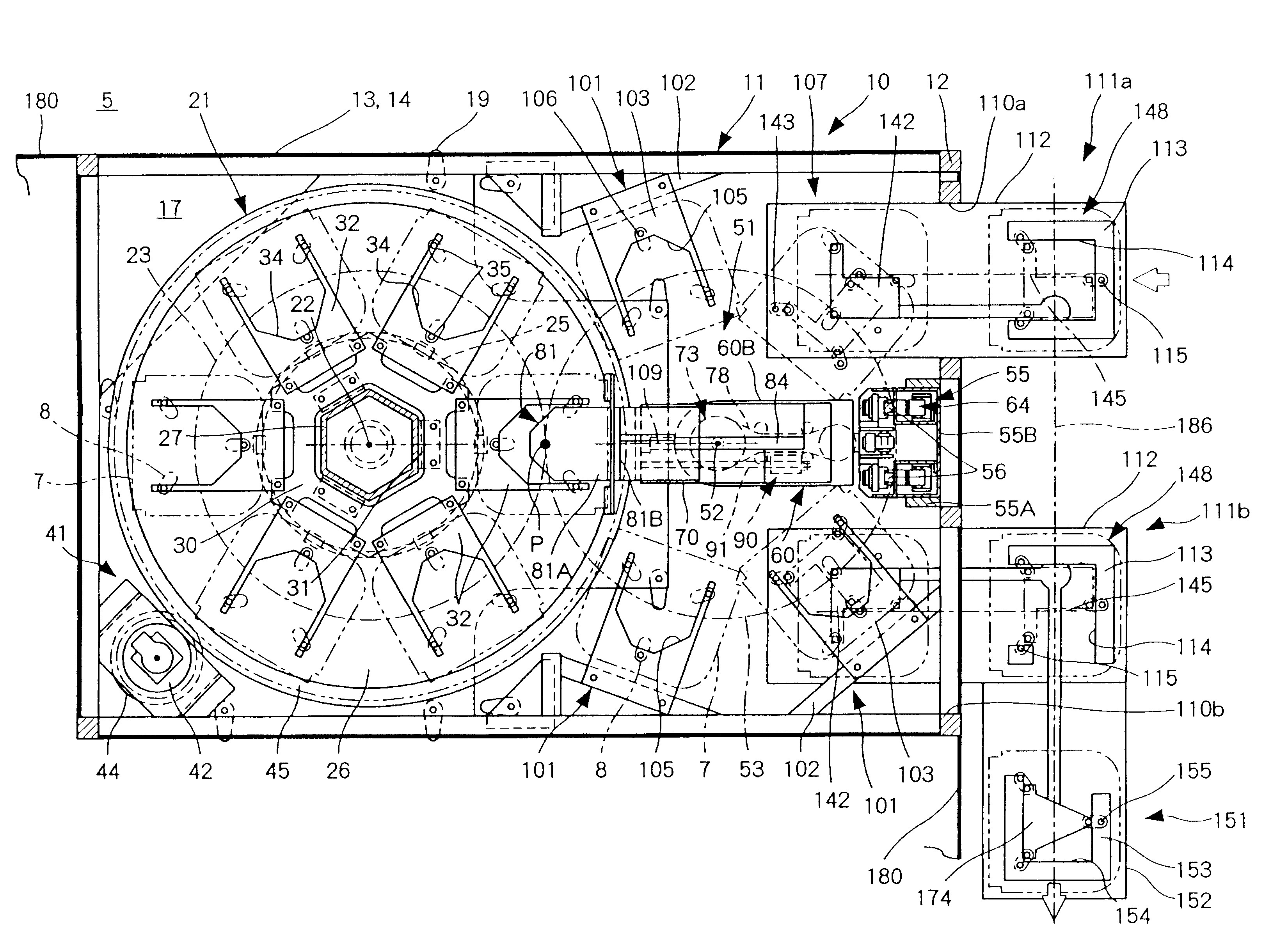
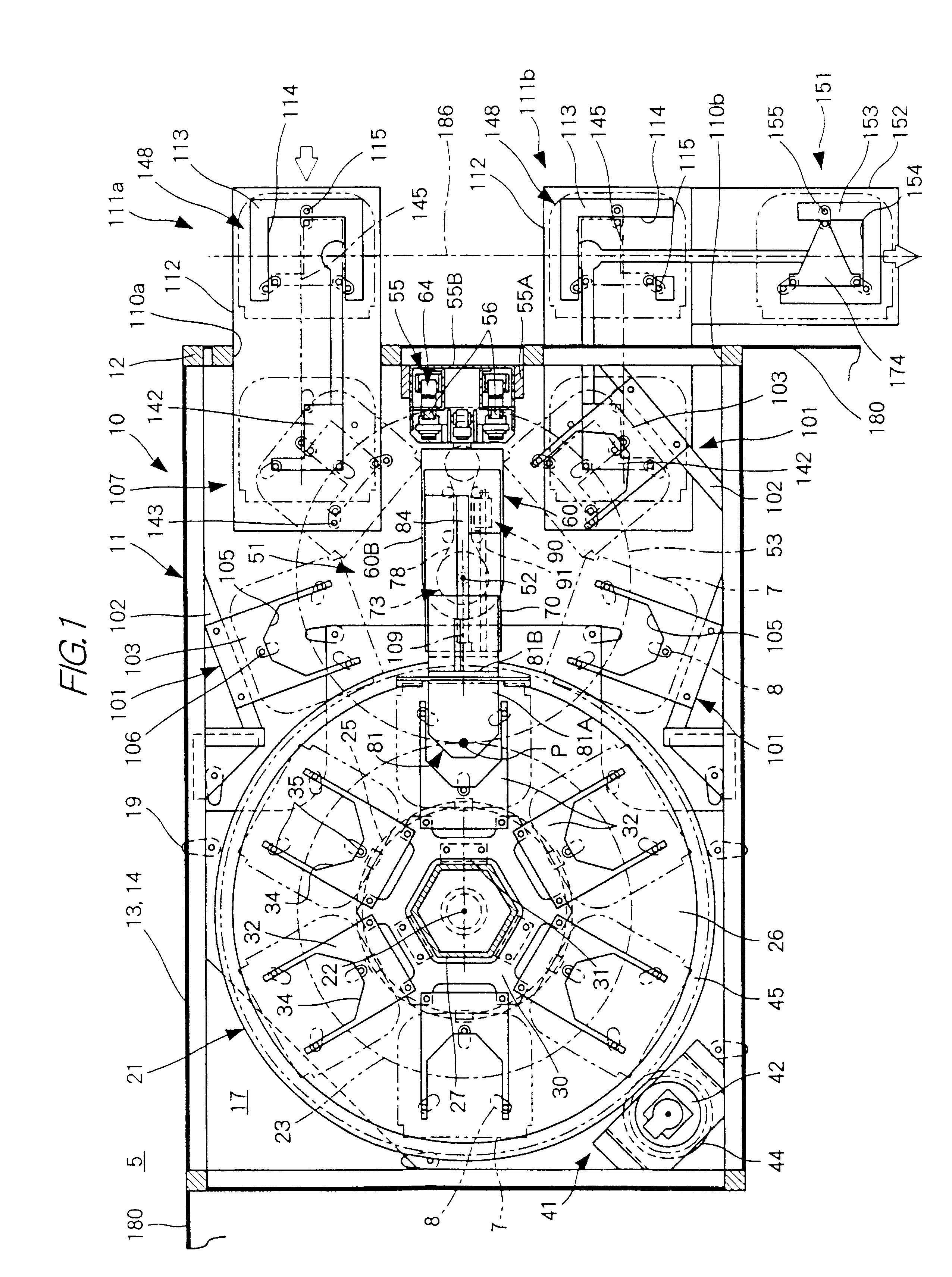
FIGS. 1-14 show load storage equipment 10 according to the present invention.

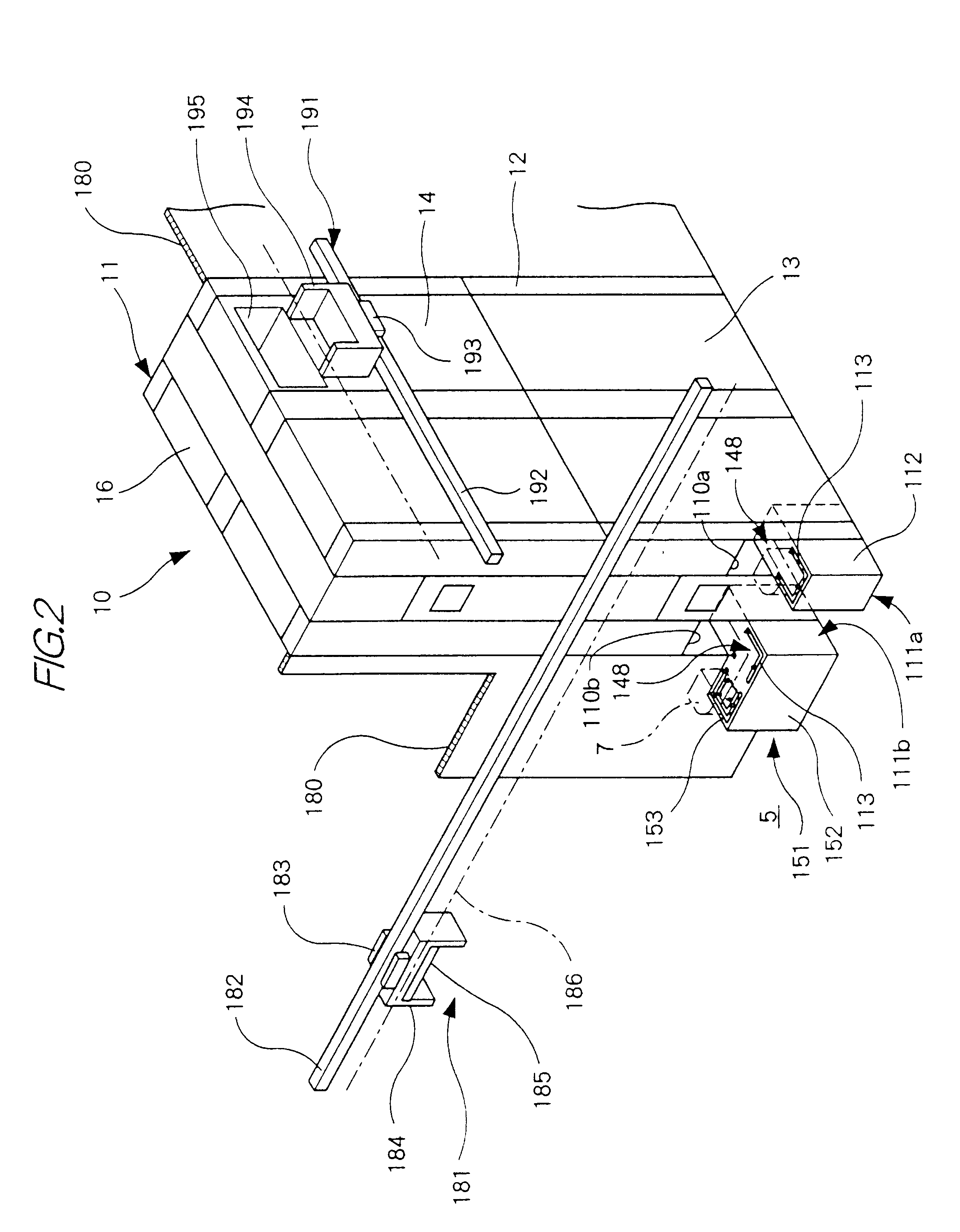
As shown in FIGS. 1-3, the storage equipment 10 includes a housing 11 in the form of a rectangular box. The storage equipment 10 also includes a rotary rack 21, a transferrer 51 and four fixed racks 101, all of which are fitted in the housing 11. The storage equipment 10 further includes an inlet port 111a and an outlet port 111b, which extend through a wall of the housing 11.

The housing 11 defines a storage chamber or space 17 in it and includes a framework 12, a lower wall 13, an upper wall 14, a base plate 15 and a top plate 16. The walls 13 and 14 surround the lower and upper halves respectively of the framework 12. The plates 15 and 16 are fixed to the bottom and top respectively of the framework 12. At least part of the walls 13 and 14, mainly the upper wall 14, may be one or more transparent plates made of resin or the like, through which it is possible to observe the condition of the storage chamber...

second embodiment

FIG. 15(a) shows load storage equipment according to the present invention. This storage equipment includes two rotary racks 21, a transferrer 51, one (or more) fixed rack 101, an inlet port 111a and an outlet port 111b. Each of the rotary racks 21 has a vertical axis 22 and a cylindrical path 23 coaxial with this axis. The transferrer 51 has a vertical axis 52 and a cylindrical path 53 coaxial with this axis. The three vertical axes 22 and 52 extend on a vertical plane 109. The transferrer 51 is interposed between the rotary racks 21. The fixed rack 101 is positioned on the cylindrical path 53 of the transferrer 51. The inner end portions of the ports 111a and 111b are positioned in a lower space formed in one of the rotary racks 21. The ports 111a and 111b are so oriented that loads can be carried into and out of the storage equipment in the horizontal directions 145 parallel to the vertical plane 109. Each of the rotary racks 21 has a transfer position P, where loads can be trans...

third embodiment

FIG. 15(b) shows load storage equipment which is a modification of the second, of the present invention. This storage equipment includes two rotary racks 21, a transferrer 51 and two (or more) fixed racks 101. The vertical axis 22 of each rotary rack 21 and the vertical axis 52 of the transferrer 51 extend on a vertical plane 109. The two vertical planes 109 make an angle with each other.

FIG. 15(c) shows load storage equipment according to a fourth embodiment, which is a modification of the second shown in FIG. 15(a), of the present invention. This storage equipment includes three rotary racks 21, a transferrer 51 and two (or more) fixed racks 101. The transferrer 51 is interposed between two of the rotary racks 21, the other of which is positioned on one side of the transferrer 51. The fixed racks 101 are positioned on the cylindrical path 53 and the other side of the transferrer 51. As is the case with the second embodiment, each of the rotary racks 21 has a transfer position P, ...


PUM


Abstract

There is provided compact load storage equipment that can store a large number of loads. The storage equipment comprises a rotary rack 21, a transferrer 51, one or more fixed racks 101, an inlet port 111a and an outlet port 111b. The rotary rack 21 is supported rotatably about a first vertical axis and includes a number of vertically arranged stages of turning load supports 32. The transferrer 51 adjoins the rotary rack 21 and includes a carrier 81, which can vertically move and rotate about a second vertical axis. The fixed racks 101 are positioned around the transferrer 51 and each includes a number of vertically arranged stages of fixed load supports 103. In plan view, the ports 111a and 111b each overlap with one of the rotary and fixed racks 21 and 101. The transferrer 51 can transfer loads between the carrier 81 and any one of the turning and fixed load supports 32 and 103, and between the carrier 81 and each of the ports 111a and 111b, by the turning and vertical movement of the carrier 81, or by the combination of the turning and vertical movement of the carrier 81 and the turning of the turning load supports 32.

Description

The present invention relates to load storage equipment for storing loads.PRIOR ARTJapanese Patent Laid-Open Publication No. H10-279,023 discloses a prior art automatic warehouse as load storage equipment. The warehouse is fitted with a pair of fixed racks extending in parallel and spaced from each other. Each of the fixed racks has a number of storage spaces or partitions arranged vertically and horizontally. The fixed racks define a traveling path between them. The warehouse is also fitted with a transferrer, which travels along the traveling path. The warehouse is further fitted with a pair of rotary racks, each of which is supported at one end of the path. Each of the rotary racks includes a number of storage spaces or partitions arranged vertically and circumferentially. The transferrer consists of a carriage, a pair of horizontal rails and a rail lifter. The carriage supports a turntable, which supports an arm, a hand or other means of transfer for transferring loads between t...

Claims


Application Information

Patent Timeline
Patent Type & Authority Patents(United States)
IPC IPC(8): B65G1/04B65G1/133B65G1/00B65G1/137B65G49/00H01L21/677
CPCB65G1/0485B65G1/137
Inventor INUI, YOSHITAKA
Owner DAIFUKU CO LTD
Why Eureka
Try Eureka