Weight measurement system, method and weight sensor

a weight measurement system and sensor technology, applied in the direction of instruments, apparatus for force/torque/work measurement, roofs, etc., can solve the problems of increasing system error rate, complicated system tasks, and unfavorable calibration types to capture zero-set shifts

Inactive Publication Date: 2004-04-20
AUTOLIV ASP INC
View PDF27 Cites 34 Cited by
  • Summary
  • Abstract
  • Description
  • Claims
  • Application Information

AI Technical Summary

Benefits of technology

A strain transducer according to the invention includes a body having two lands with an elastomeric beam in juxtaposition with the two lands. The mass of the elastomeric beam is less than the mass of either of the lands. The elastomeric beam has a region of minimum thickness and one or more regions of maximum thickness. An electrically resistive body is located on the elastomeric beam overlying the region of minimum thickness. First and second electrical contacts electrically contact spaced part locations of the resistive body, whereby deformation of the elastomeric beam results in a change in electrical resistance of the electrically resistive body between said first and second electrical contacts.

Problems solved by technology

This type of calibration is unlikely to capture a shift in zero set as a result of over stressing of the weight sensor during vehicle use, aging of components, and other drift causing factors that occur throughout the lifetime of the vehicle.
Thus, such one-time calibration systems will over time result in a shift in weight measurement readings that increase the system error rate as the vehicle ages.
Two strain gauges have complicated the system tasks of measuring weight, compensation, and calibration.
This affects the complexity and cost of system hardware and software.

Method used


Image

  • Weight measurement system, method and weight sensor
  • Weight measurement system, method and weight sensor
  • Weight measurement system, method and weight sensor

Examples


Embodiment Construction

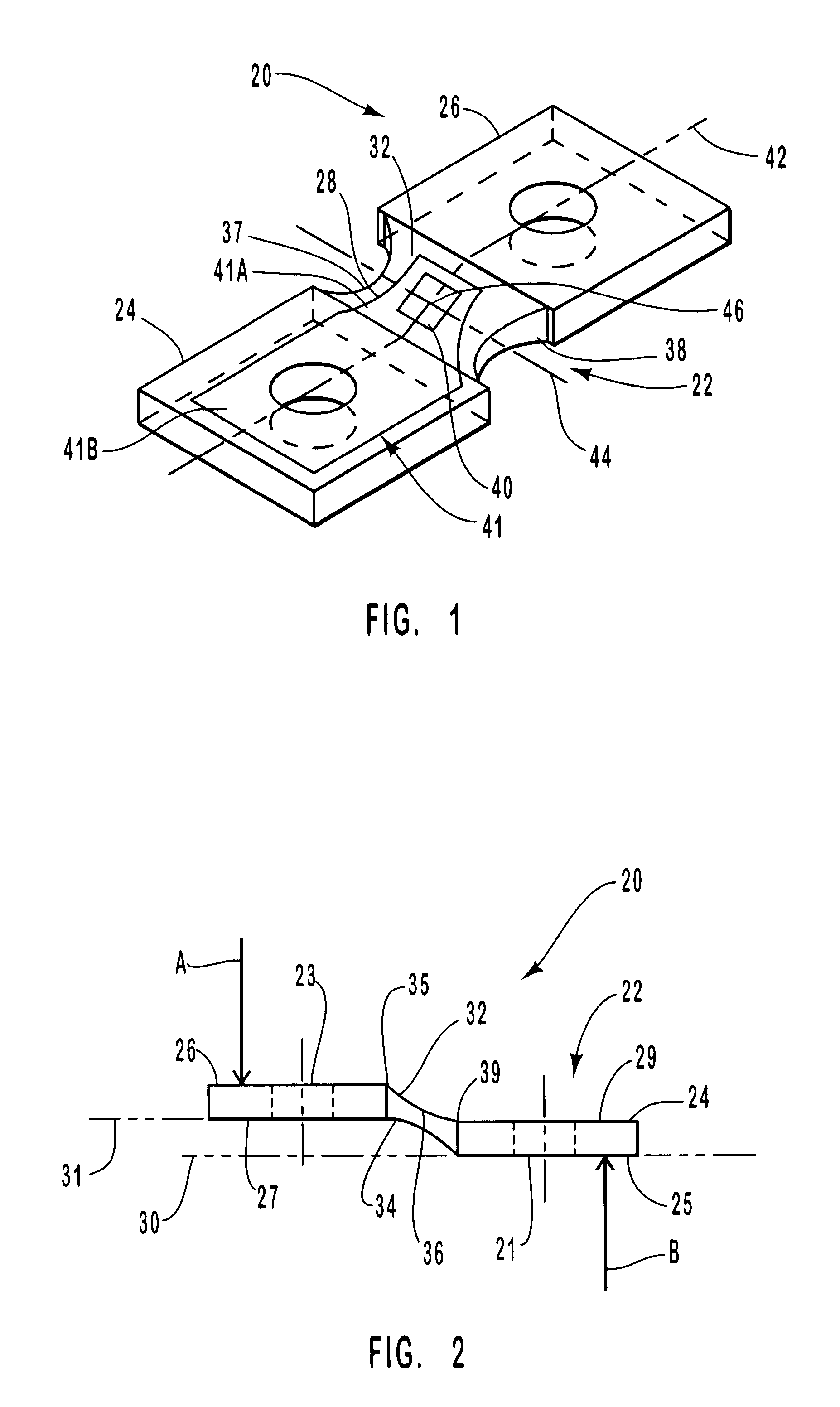
With reference to FIGS. 1 and 2, there is provided a strain transducer 20 according to the present invention. Transducer 20 has an integral body 22 and a strain gauge element 40. Integral body 22 includes a first land 24 and a second land 26 that are joined by an elastomeric beam 28 that deforms when stressed, but, due to its elasticity, returns to its original shape when the stress is removed.

First land 24 has a bottom surface 25 that lies in a plane identified by line 30 in FIG. 2. Second land 26 has a bottom surface 27 that lies in a plane identified by line 31. Planes 30 and 31 are substantially parallel. Elastomeric beam 28 joins first and second lands 24 and 26. Elastomeric beam 28 has a first surface 32 and a second opposed surface 34. First land 24 and second land 26 have masses that are each substantially larger than the mass of elastomeric beam 28. To this end, first and second surfaces 32 and 34 are shaped to produce a region 36 of minimum thickness and one or more region...


PUM


Abstract

A weight measurement system for automatically calibrating weight sensors installed on a motor vehicle seat. The system performs a calibrate operation whenever a valid weight measurement window is found. A valid weight measurement window is defined by the seat being empty, an associated door being open and an associated seat buckle being unlatched. The system operates in a factory install mode to establish a reference zero set value and in a diagnostic mode to establish a temporary zero set value that reflects drift of the weight sensors. The temporary zero set value is used by a weight management program to control occupant restraint devices. The weight sensor has an integral body with two lands connected by an elastomeric beam. The elastomeric beam has a pair of opposed surfaces that define a region of minimum thickness and one or more regions of maximum thickness. A resistive strain gauge element is disposed on the region of minimum thickness. The system measures changes in the resistance of the weight sensor caused by weight of the seat.

Description

BACKGROUND OF INVENTION1. Field of InventionThis invention relates to a system that measures weight in a seat of a motor vehicle, weight sensors or strain transducers used in the system and the calibration of the weight sensors. In particular, the invention relates to a method and system of calibrating weight sensors used in motor vehicles and to a transducer that can be used as a weight sensor in the system.2. Description of Prior ArtWeight sensors are used in a motor vehicle seat to measure strain or stress as a result of weight in the seat. The amount of measured stress is processed with other information, such as in seat occupant positioning, to control primary and supplemental restraint systems, such as managed load limiters, pre-tensioners and / or side and frontal air bags. Accurate weight in seat information combined with supporting primary and supplemental restraints improves overall system decisions and performance of the system in protecting occupants of the vehicle should ...

Claims


Application Information

Patent Timeline
Patent Type & Authority Patents(United States)
IPC IPC(8): B60N2/00B60R21/01G01G19/40G01G19/414G01G23/00G01G23/01B60R21/013B60R21/015
CPCB60N2/002G01G19/4142G01G23/01B60R21/01516B60R21/01504B60R21/0152B60R21/013B60R2021/01211B60R2021/01218
Inventor KNOX, MATTHEW J.KOPITZKE, DANIEL F.
Owner AUTOLIV ASP INC
Why Eureka
Try Eureka