Method and apparatus for providing three axis magnetic bearing having permanent magnets mounted on radial pole stack

a technology of permanent magnets and magnetic bearings, which is applied in the direction of bearings, shafts and bearings, dynamo-electric components, etc., can solve the problems of inability to actively control the radial position, current techniques for manufacturing magnetic bearings using radial magnetized permanent magnets require costly assembly and alignment procedures, and achieve high linear magnetic bias, minimize air gap, and the effect of high for

Inactive Publication Date: 2004-04-27
CALNETIX TECH +1
View PDF1 Cites 115 Cited by
  • Summary
  • Abstract
  • Description
  • Claims
  • Application Information

AI Technical Summary

Benefits of technology

The present invention provides an improved magnetic bearing that uses permanent magnets to provide the bias flux with electromagnetic coils providing the control flux, bias flux being a constant magnetic flux which energizes the bearing airgaps. The control magnetic flux adds flux from one pole and subtracts flux from the opposite axis pole to produce a net force on a target piece located on the bearing shaft. Bias magnetic field is present to allow for linear control of force using the control input current, the input current being converted to magnetic flux by the control electromagnets in the magnetic bearing. Providing bias magnetic flux using permanent magnets reduces the required bearing input power (by eliminating a bias electromagnet) and provides a highly linear magnetic bias field in the airgap throughout the bearing radial and axial airgaps. The magnetic circuits generating the control and bias fluxes are substantially non-coincident but share a path over some portions that include radial and axial airgaps, allowing for a low reluctance, efficient path for the electromagnetic flux. The flux paths of the permanent magnets are completely defined with minimized airgaps for achieving higher forces, small size and minimum cost. The non-coincident control flux path allows for very low control currents to produce extremely large forces very efficiently. A single coil and amplifier for control of the axial force and two coils with one associated amplifier for each radial axis of control provides simplicity and cost effectiveness. A single target disk is utilized and is reacted against for both radial and axial forces. Radially magnetized permanent magnets are not required and permanent magnets are not attached to the rotor. The permanent magnets used in the present invention are first fabricated and then axially magnetized as square segments or as a ring prior to being mounted on the sides of the stator central pole, providing an effective and inexpensive technique for manufacturing magnetic bearings.

Problems solved by technology

However, the system set forth in the copending application does not allow for active radial position control.
Current techniques for manufacturing magnetic bearings using radial magnetized permanent magnets require costly and difficult assembly and alignment procedures.

Method used


Image

  • Method and apparatus for providing three axis magnetic bearing having permanent magnets mounted on radial pole stack
  • Method and apparatus for providing three axis magnetic bearing having permanent magnets mounted on radial pole stack
  • Method and apparatus for providing three axis magnetic bearing having permanent magnets mounted on radial pole stack

Examples


Embodiment Construction

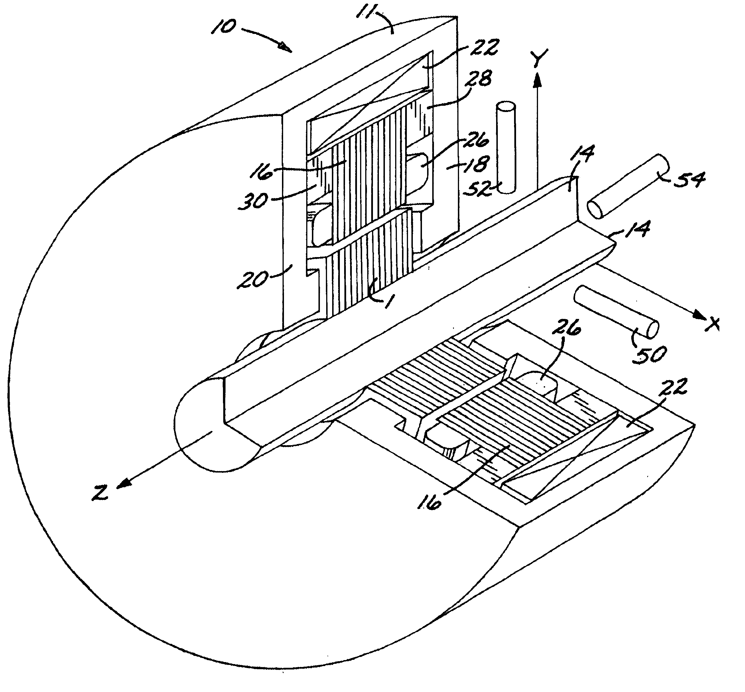
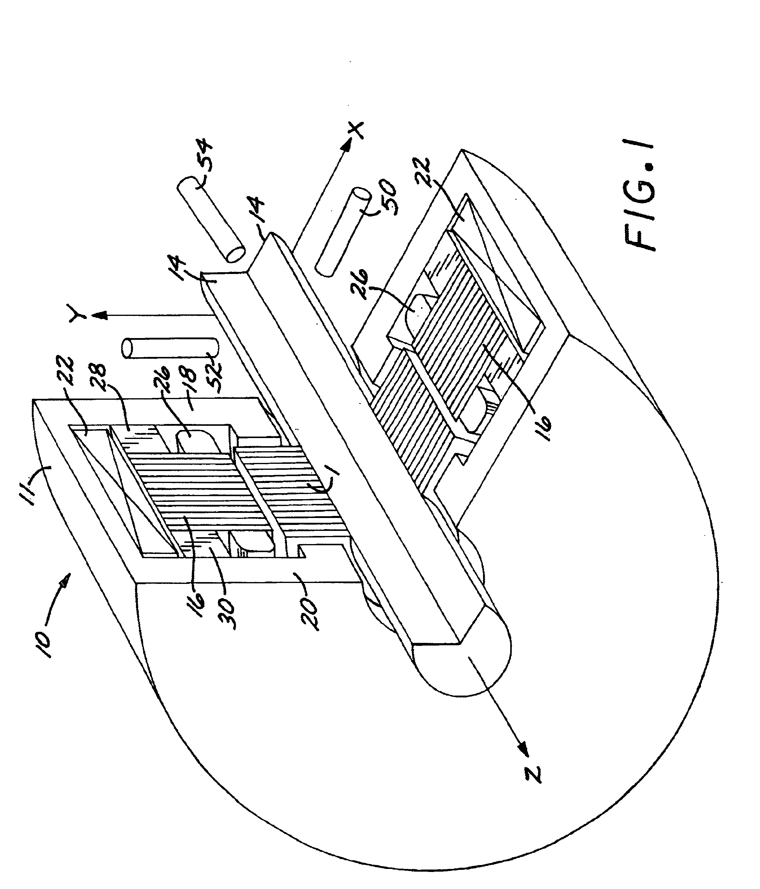
The following sets forth the general operating principles of a magnetic thrust bearing of the type disclosed in U.S. Pat. No. 5,514,924 to place the present invention in proper perspective. The teachings of the '924 patent and copending application Ser. No. 09 / 865015 necessary for an understanding of the present invention is incorporated herein by reference.

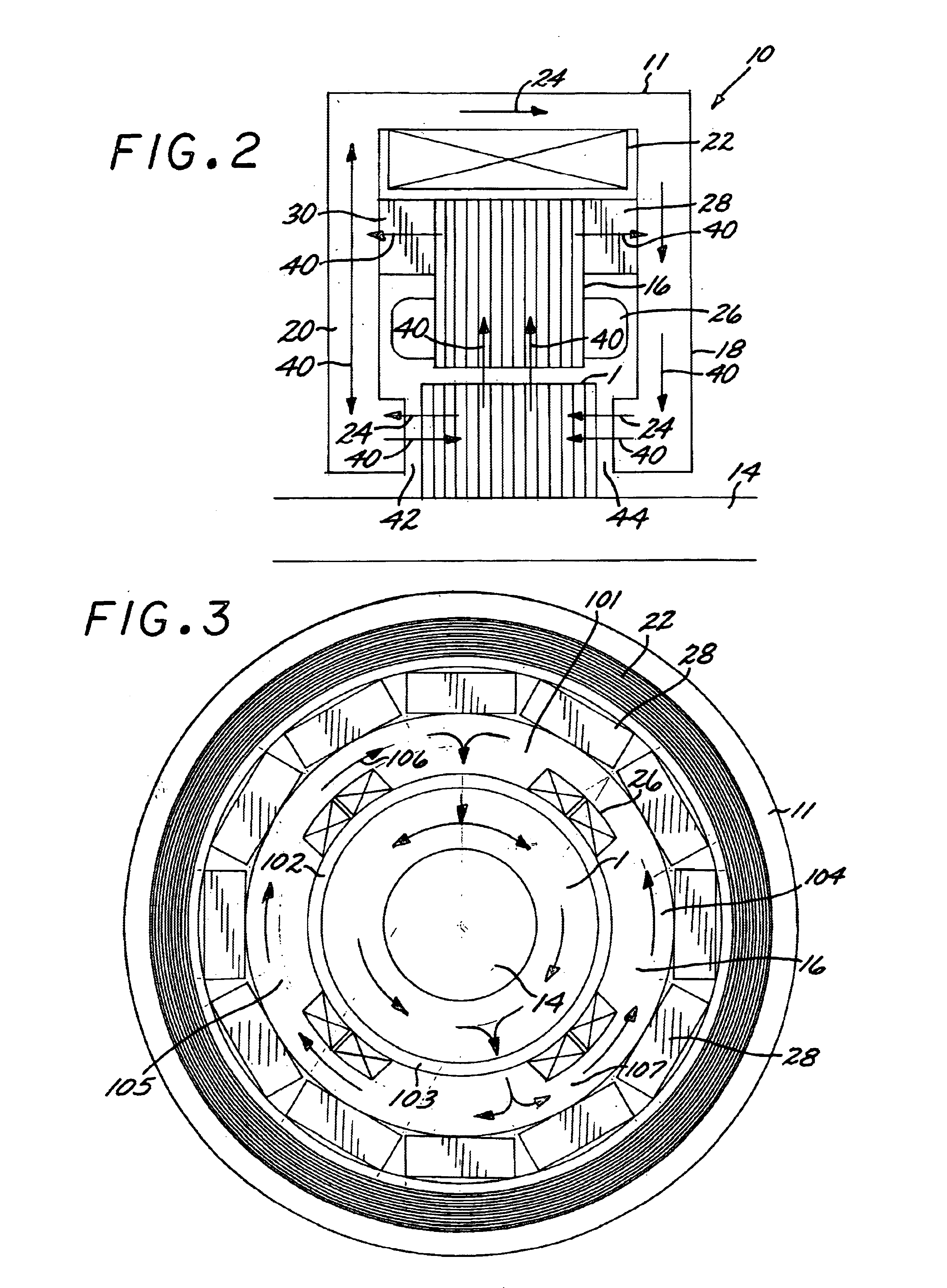
Referring now to FIGS. 1-3, the magnetic flux 40 generated by the permanent magnets 28 and 30 in the magnetic thrust bearing 10 of the present invention is directed axially through axial air gaps 42 and 44 to provide axial magnetic flux coupling of the shaft 14 to the stator assembly 11. Similarly, the magnetic flux 40 is then directed radially through the radial airgaps to provide radial magnetic flux coupling of the rotor disk 1 to the stator assembly 11. The rotor disk 1 is mechanically attached to the shaft 14 to effectively transmit forces applied to disk 1 to the shaft 14.

The active radial control electromagnet coils 26 pos...


PUM


Abstract

An improved magnetic bearing that uses permanent magnets to provide the bias flux. The magnetic circuits generating the control flux and bias fluxes are substantially non-coincident but share the same path over some portions that include radial and axial airgaps allowing for a low reluctance and an efficient path for the electromagnetic flux. The flux paths of the permanent magnets are completely defined with minimized airgaps for achieving higher forces and efficiency and very low control currents that produce extremely large forces. A single coil and amplifier for the axial force control and two coils with one associated amplifier for each radial axis of control provides simplicity and cost effectiveness. A single thrust disk is provided that is reacted against for both radial and the axial displacement. The permanent magnets used in the present invention are first fabricated and axially magnetized as segments or as continuous rings prior to being mounted on the sides of the rotor pole, providing an effective and inexpensive technique of manufacturing magnetic bearings.

Description

1. Field of the InventionThe present invention provides a three-axis magnetic bearing utilizing a permanent magnet to generate the bias flux and wherein the magnets are mounted to the face of the pole stack.2. Description of the Prior ArtCopending application Ser. No. 09 / 865,015 filed May 23, 2001, invented by the inventor of the instant application, discloses and claims a magnetic thrust bearing using a single coil and linear amplifier and a single thrust desk. The design set forth in the copending application does not utilize permanent magnets, and more specifically, axially magnetized permanent magnets that are not attached to the rotor, for reduced cost and simplified construction when compared to existing thrust bearings.Although the design set forth in the copending application provides significant advantages over the prior art designs described therein, it is desirable to provide a magnetic bearing wherein magnetized permanent magnetic members are utilized to provide the magn...

Claims


Application Information

Patent Timeline
Patent Type & Authority Patents(United States)
IPC IPC(8): F16C39/06F16C39/00
CPCF16C32/0465F16C32/0485
Inventor MCMULLEN, PATRICK T.HUYNH
Owner CALNETIX TECH
Why Eureka
Try Eureka