Heads-up display system with optical rotation layers

a display system and optical rotation technology, applied in the field of display systems, can solve the problems of forming a double image, which is difficult to be observed by a driver, and is impossible to prevent the formation of a double imag

Inactive Publication Date: 2004-06-01
CENT GLASS CO LTD +1
View PDF7 Cites 118 Cited by
  • Summary
  • Abstract
  • Description
  • Claims
  • Application Information

AI Technical Summary

Problems solved by technology

However, with this head-up display system, reflection of light of an image is unavoidably made on the front-side or rear-side surface of the glass plate thereby forming a double image which is difficult to

Method used


Image

  • Heads-up display system with optical rotation layers
  • Heads-up display system with optical rotation layers
  • Heads-up display system with optical rotation layers

Examples


Embodiment Construction

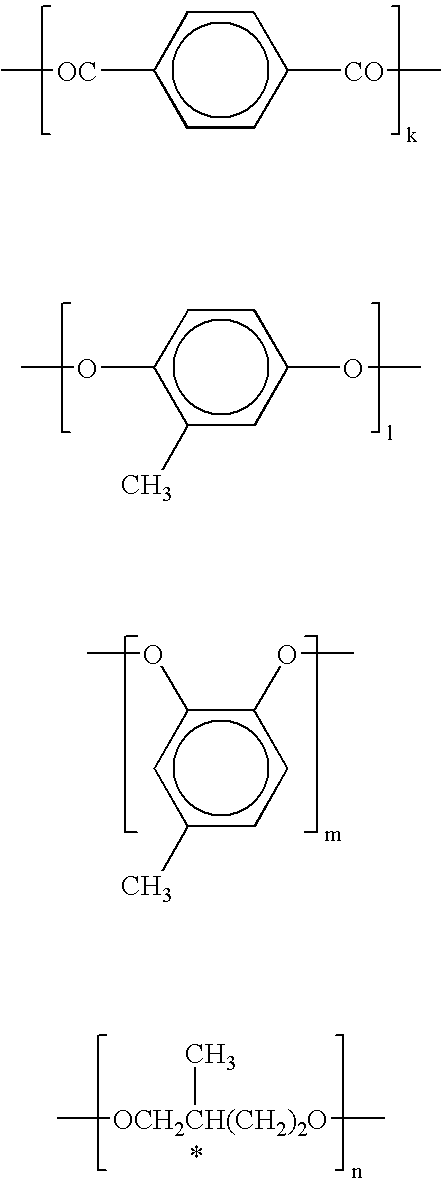
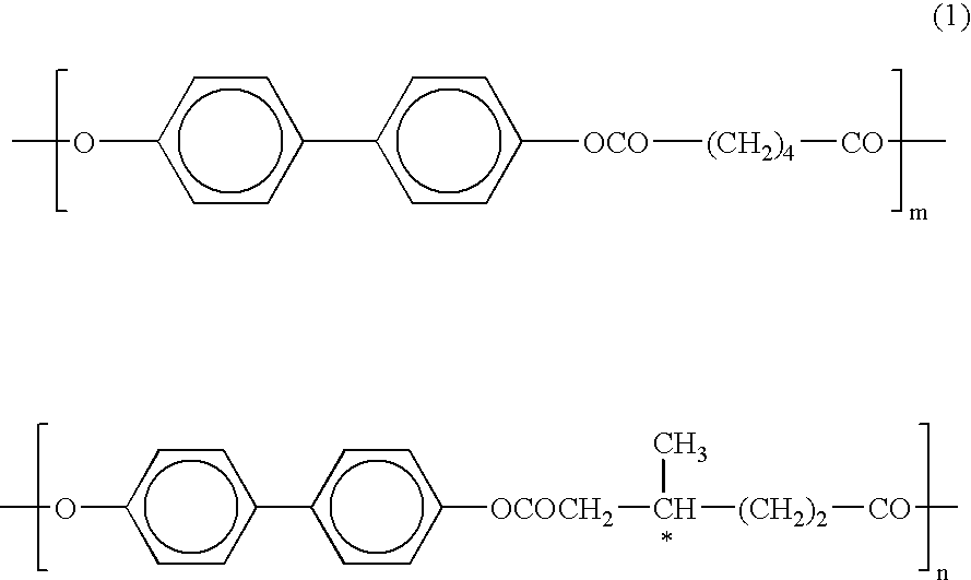
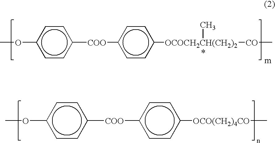
Referring now to FIG. 1 of the drawings, a first embodiment of a display system according to the present invention is illustrated by the reference character S. The display system S of this embodiment is a head-up display system and constituted by incorporating optical rotation (polarization-direction changing) layer or films 2, 7. The optical rotation layers 2, 7 are adapted to change the direction of polarization of light to be incident thereon, i.e., to rotate a plane of polarization of light to be incident thereon. The optical rotation layers 2, 7 in this embodiment are formed of a liquid crystal polymer which is in twisted nematic orientation under a liquid crystal condition and is in a glassy state at a temperature lower than liquid crystal transition point thereof.

The optical rotation (polarization-direction changing) layers 2, 7 are formed as follows: The liquid crystal polymer is coated on a transparent substrate (substrate film) such as a plastic film formed of, for example...


PUM


Abstract

A head-up display system comprising a transparent plate. A liquid crystal display generates a display light of information with a plane of polarization inclined by about 45.degree. relative to an image plane vertical axis. A first optical rotation layer is disposed on a first surface of the transparent plate, and receives the display light from the liquid crystal display and optically rotates the plane of polarization of the display light by about 90.degree.. A second optical rotation layer is between the image plane of the liquid crystal display and a second surface of the transparent plate, and optically rotates the plane of polarization of the display light by about 45.degree. and allows S-polarized light to emanate toward the transparent plate at Brewster's angle. The S-polarized light is reflected on the second surface and is directed toward an eye of an operator.

Description

BACKGROUND OF THE INVENTION1. Field of the InventionThis invention relates to improvements in a display system for optically projecting a display light of information to be observed by a person from a liquid crystal display as a display device, and more particularly to the display system such as a head-up display system which is configured, for example, such that an operator and the like can observe an image of driving information projected as the display light on a windshield glass or on a combiner provided on the windshield glass while looking a frontal view through the windshield glass in such a manner that the driving information is superimposed on the frontal view, in a vehicle or a ship, or the like display system for architecture.2. Description of the Prior ArtA variety of head-up display systems of an automotive vehicle have been hitherto proposed and put into practical use. A typical head-up display system is constituted by directly applying a film functioning as a half mir...

Claims


Application Information

Patent Timeline
IPC IPC(8): G02B27/01G02F1/1335G02F1/13G02B27/00G02F1/13357
CPCG02B27/0101G02F1/13362G02B2027/012
Inventor ASAKURA, MOTOHHOSAKI, KENJI
Owner CENT GLASS CO LTD
Why Eureka
Try Eureka