Apparatus and method for alternate path system

a technology of alternate path and apparatus, applied in the direction of borehole/well accessories, drilling pipes, drilling rods, etc., can solve the problems of increasing operational and maintenance expenses, reducing production rates and damage to subsurface production equipment, and affecting the operation of the system

Inactive Publication Date: 2004-06-22
SCHLUMBERGER TECH CORP
View PDF27 Cites 85 Cited by
  • Summary
  • Abstract
  • Description
  • Claims
  • Application Information

AI Technical Summary

Problems solved by technology

Sand or silt flowing into the wellbore from unconsolidated formations can lead to an accumulation of fill within the wellbore, reduced production rates and damage to subsurface production equipment.
Due to its highly abrasive nature, sand contained within production streams can result in the erosion of tubing, flowlines, valves and processing equipment.
The problems caused by sand production can significantly increase operational and maintenance expenses and can lead to a total loss of the well.
A problem that is frequently encountered in a gravel pack completion, especially in long or highly deviated sections, is the formation of gravel bridges in the annulus between the wellbore and the tubing string.
Non-uniform gravel packing of the annulus between the screen and the wellbore often occurs as a result of the premature loss of carrier fluid from the slurry.
These gravel bridges can further restrict the flow of slurry through the annulus, which can result in voids within the gravel pack.
Once the well is placed on production, the flow of produced fluids will tend to be concentrated through any voids in the gravel pack, which can result in the migration of fines and sand into the produced fluids and lead to the problems discussed above.
Over time the gravel that is deposited within the annulus may have a tendency to settle and fill any void areas, thereby loosening the gravel pack that is located higher up in the wellbore, and potentially creating new voids in areas adjacent to producing formations.
Having to make two separate connections, the sand screens and the conduits, is time consuming and results in increased rig time and cost.

Method used


Image

  • Apparatus and method for alternate path system
  • Apparatus and method for alternate path system
  • Apparatus and method for alternate path system

Examples


Embodiment Construction

Illustrative embodiments of the invention are described below. In the interest of clarity, not all features of an actual implementation are described in this specification. It will of course be appreciated that in the development of any such actual embodiment, numerous implementation-specific decisions must be made to achieve the developers' specific goals, such as compliance with system-related and business-related constraints, which will vary from one implementation to another. Moreover, it will be appreciated that such a development effort might be complex and time-consuming, but would nevertheless be a routine undertaking for those of ordinary skill in the art having the benefit of this disclosure.

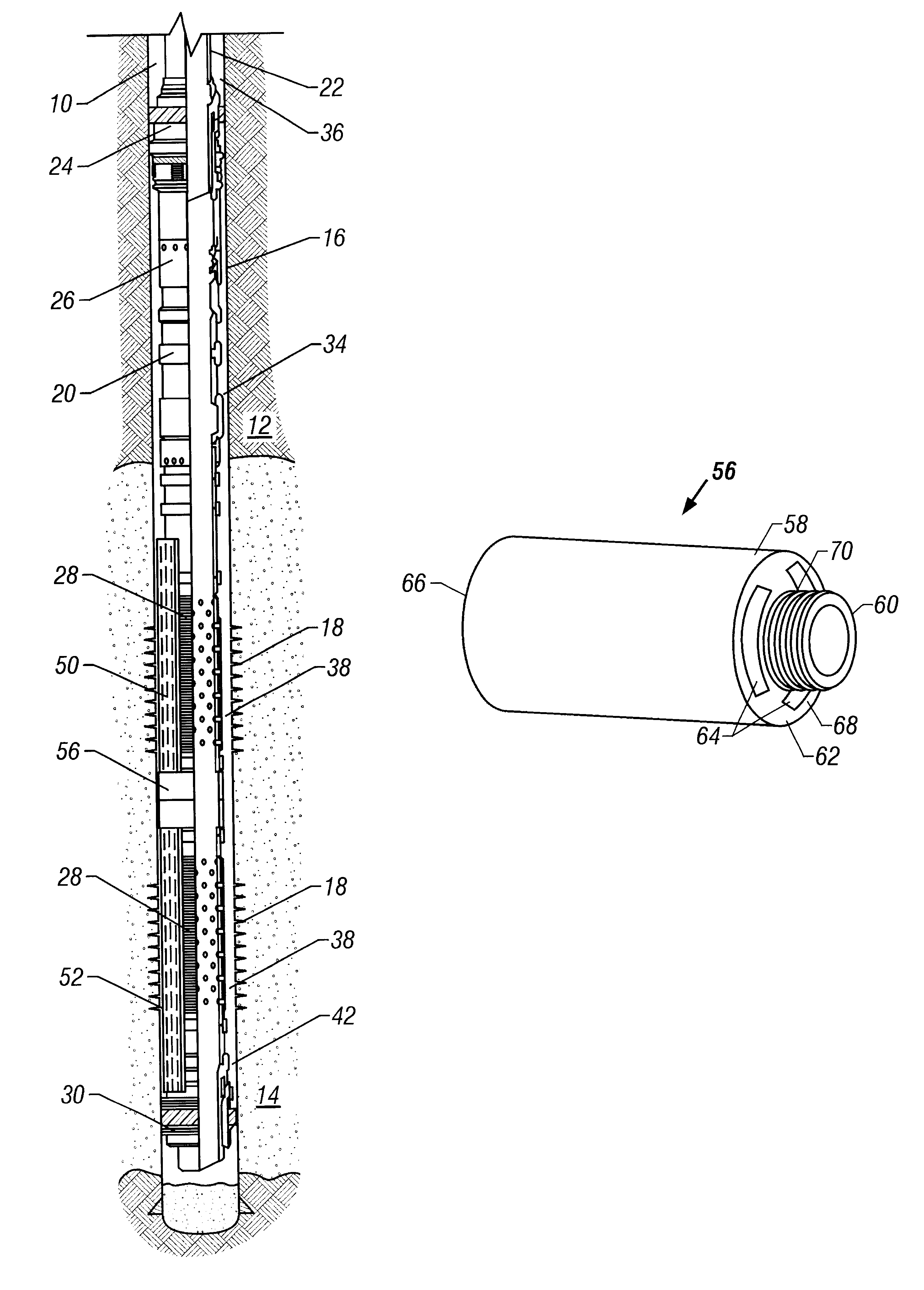
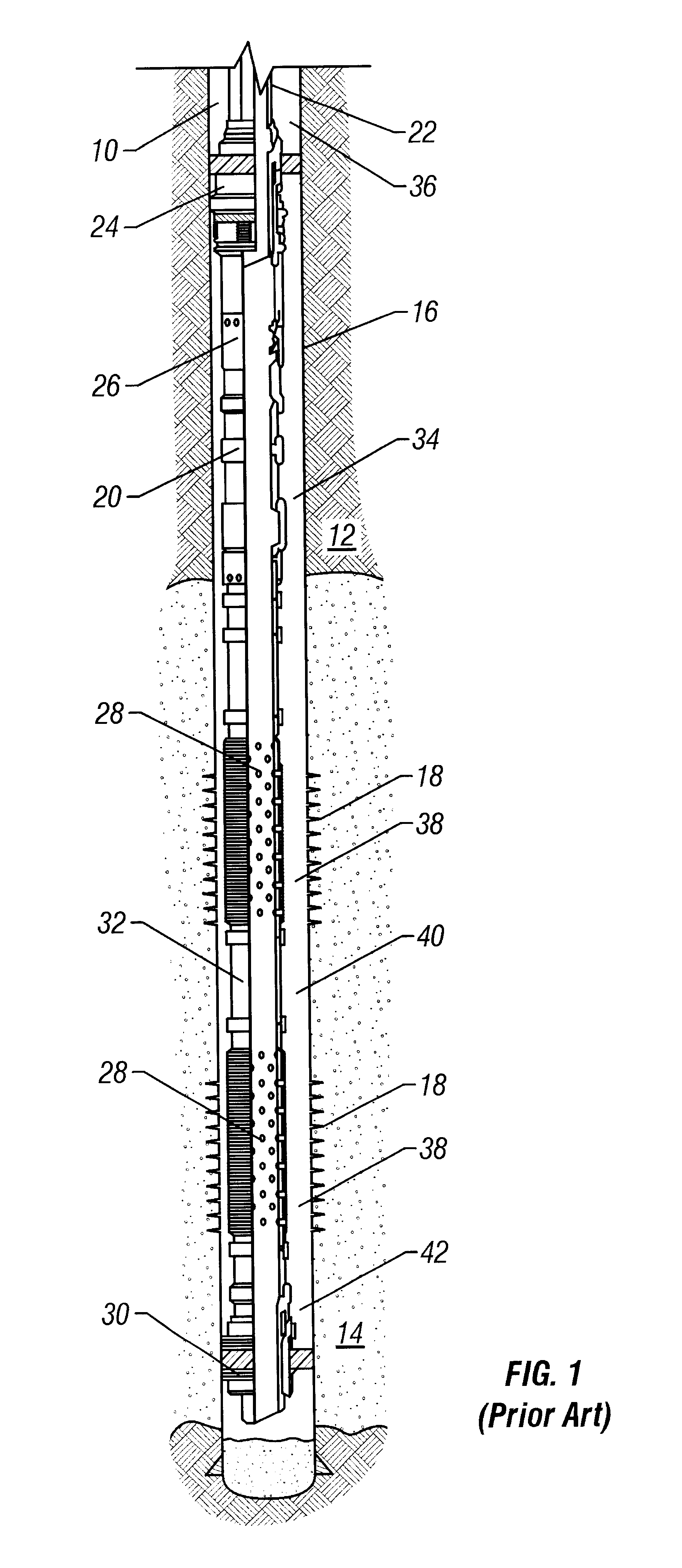
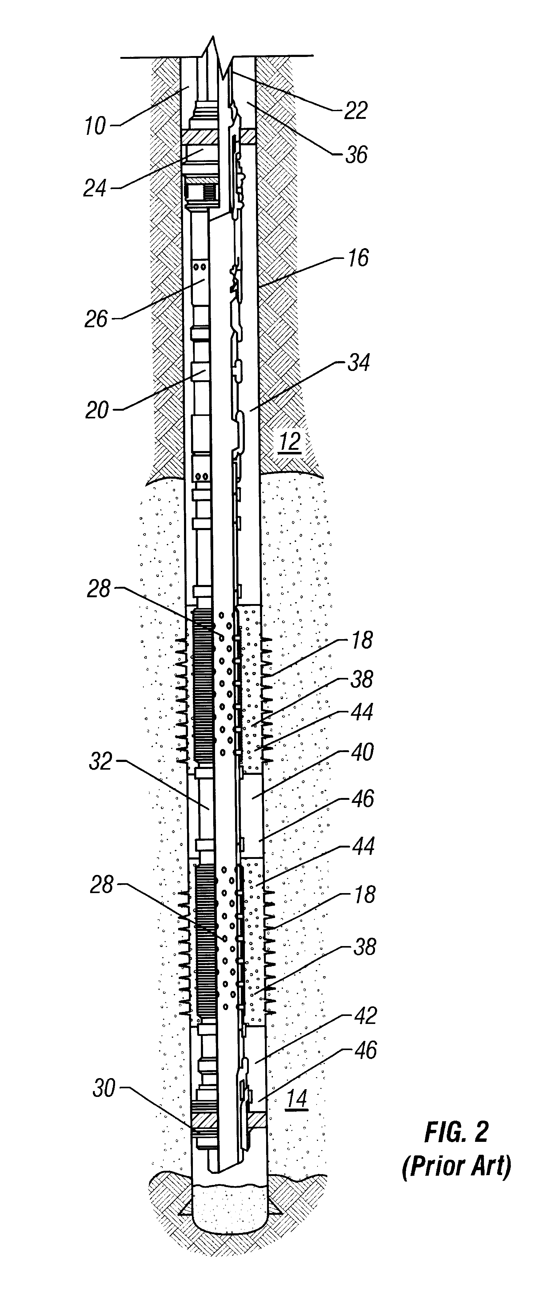
Referring to the attached drawings, FIG. 1 illustrates a cross-sectional view of a wellbore 10 that has penetrated a subterranean zone 12 that includes a productive formation 14. The wellbore 10 has a casing 16 that has been cemented in place. The casing 16 has a plurality of perforati...


PUM


Abstract

This invention includes an apparatus and method for completing a subterranean zone penetrated by a wellbore. One embodiment of the invention is an apparatus for connecting a first sand screen assembly and a second sand screen assembly. The apparatus comprises a tubular housing having an eccentric longitudinal bore therethrough, providing a first fluid communication path through the apparatus, the longitudinal bore defining a housing wall. A longitudinal passageway is disposed within the housing wall, providing a second fluid communication path through the apparatus. The first fluid communication path is capable of communicating fluid flow from a sand screen in the first sand screen assembly to a sand screen in the second sand screen assembly. The second fluid communication path is capable of communicating fluid flow from an alternate path element in the first sand screen assembly an alternate path element in the second sand screen assembly.

Description

1. Field of the InventionThis invention relates generally to tools used to complete subterranean wells and more particularly relates to apparatus and methods for use in performing gravel pack operations.2. Description of Related ArtHydrocarbon fluids such as oil and natural gas are obtained from a subterranean geologic formation, referred to as a reservoir, by drilling a well that penetrates the hydrocarbon-bearing formation. Once a wellbore has been drilled, the well must be completed before hydrocarbons can be produced from the well. A completion involves the design, selection, and installation of equipment and materials in or around the wellbore for conveying, pumping, or controlling the production or injection of fluids. After the well has been completed, production of oil and gas can begin.Sand or silt flowing into the wellbore from unconsolidated formations can lead to an accumulation of fill within the wellbore, reduced production rates and damage to subsurface production equ...

Claims


Application Information

Patent Timeline
Patent Type & Authority Patents(United States)
IPC IPC(8): E21B17/02E21B17/00E21B17/18E21B43/02E21B43/04
CPCE21B17/02E21B17/18E21B43/045
Inventor DANOS, JAKE A.HURST, GARY D.
Owner SCHLUMBERGER TECH CORP
Why Eureka
Try Eureka