Apparatus and process for analyzing a stream of fluid

a fluid and apparatus technology, applied in the direction of porous material analysis, instruments, investigating moving fluids/granular solids, etc., can solve the disadvantageous increase in complexity and expense of the analyzing system, the complexity of the prior known devices, and the inability to control and monitor the test fluid. , to achieve the effect of convenient operation and deployment, convenient deployment, and convenient manufacturing

Inactive Publication Date: 2004-08-31
HAMILTON ASSOCS
View PDF33 Cites 22 Cited by
  • Summary
  • Abstract
  • Description
  • Claims
  • Application Information

AI Technical Summary

Benefits of technology

An object of a preferred embodiment of the present invention is to provide a novel and unobvious apparatus and process for analyzing a stream of fluid to determine one or more characteristics of particles suspended in the fluid stream.
Another object of a preferred embodiment of the present invention is to provide an apparatus for analyzing a fluid stream that can readily be deployed in an environment with only minimal adaptation of the environment.
Yet another object of one preferred embodiment of the present invention is provide an apparatus for analyzing a fluid stream that can be used in a hazardous environment without any appreciable degradation in the accuracy of the apparatus.
A further object of a preferred embodiment of the present invention is to provide an apparatus for analyzing a fluid stream that can readily direct electromagnetic radiation to a point in a scattering chamber without the use of lenses.
Still a further object of a preferred embodiment of the present invention is to provide an apparatus for analyzing a fluid stream that is relatively easy to manufacture.
Yet still a further object of a preferred embodiment of the present invention is to provide an apparatus for analyzing a fluid stream that is relatively easy to operate and deploy in the field.

Problems solved by technology

The complexity of these prior known devices has necessitated the use of very skilled laborers to manufacture, operate and deploy known particle analyzers to analyze particles in a given fluid stream.
These prior devices are disadvantageous, inter alia, because the remote location of the scattering region or chamber makes it more difficult to control and monitor the test fluid and the light used to irradiate the test fluid.
Accordingly, the complexity and expense of the analyzing system is disadvantageously increased.
Prior known particle analyzers have suffered greatly in accuracy and durability due to their deployment in hazardous test environments.
Such hazardous environments subject the particle analyzer to extremely high pressures, temperatures and / or highly corrosive conditions.
By deploying optical elements directly into the hazardous environment, the accuracy and durability of the prior known particle analyzers have been compromised.
These constructions are disadvantageous because the additional component requires further adaptation of the environment in which the particle analyzer is deployed.
Moreover, the additional component adds to the complexity and expense of the particle analyzer.

Method used


Image

  • Apparatus and process for analyzing a stream of fluid
  • Apparatus and process for analyzing a stream of fluid
  • Apparatus and process for analyzing a stream of fluid

Examples


Embodiment Construction

The most preferred form of the invention will now be described with reference to FIGS. 1-8. The appended claims are not limited to the most preferred embodiment and no term used herein is to be given a meaning other than its ordinary meaning unless accompanied by a statement that the term "as used herein is defined as follows".

FIGS. 1 Through 4

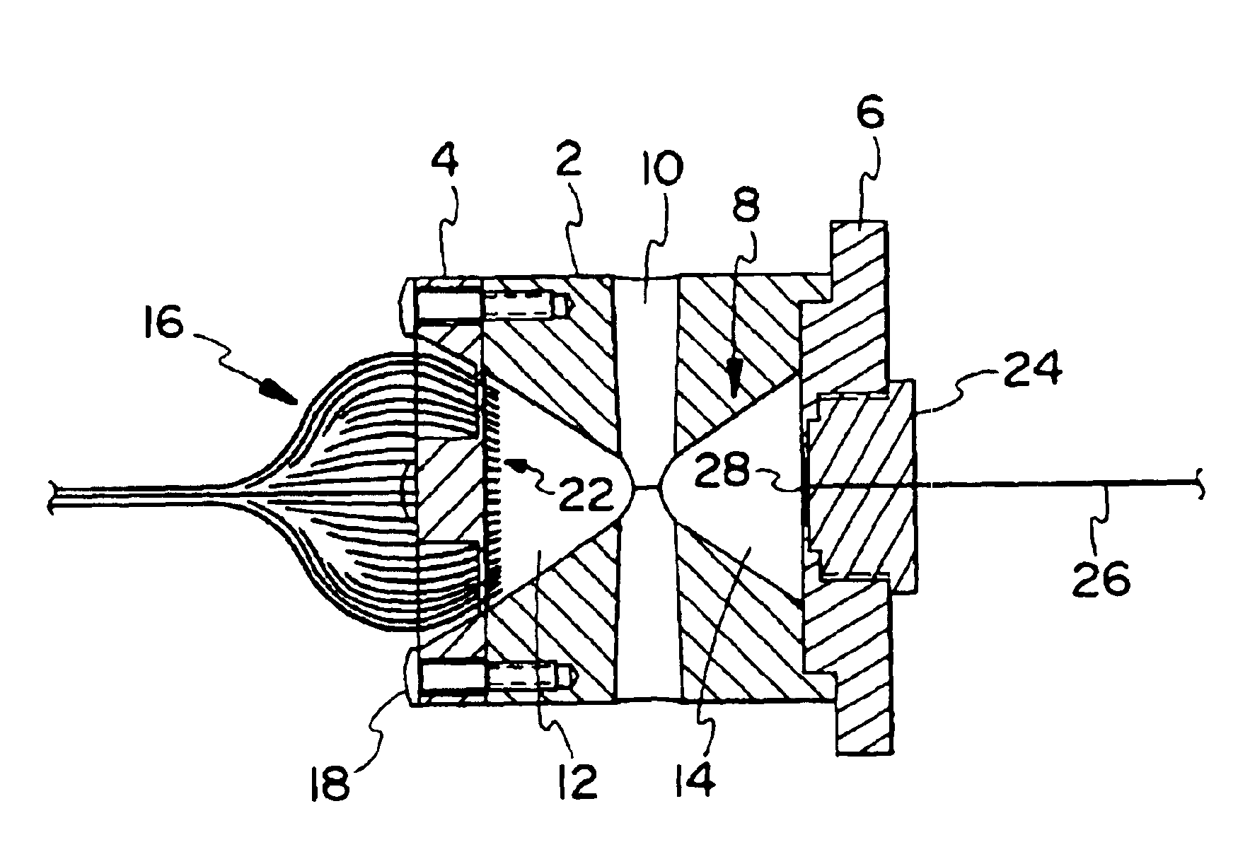
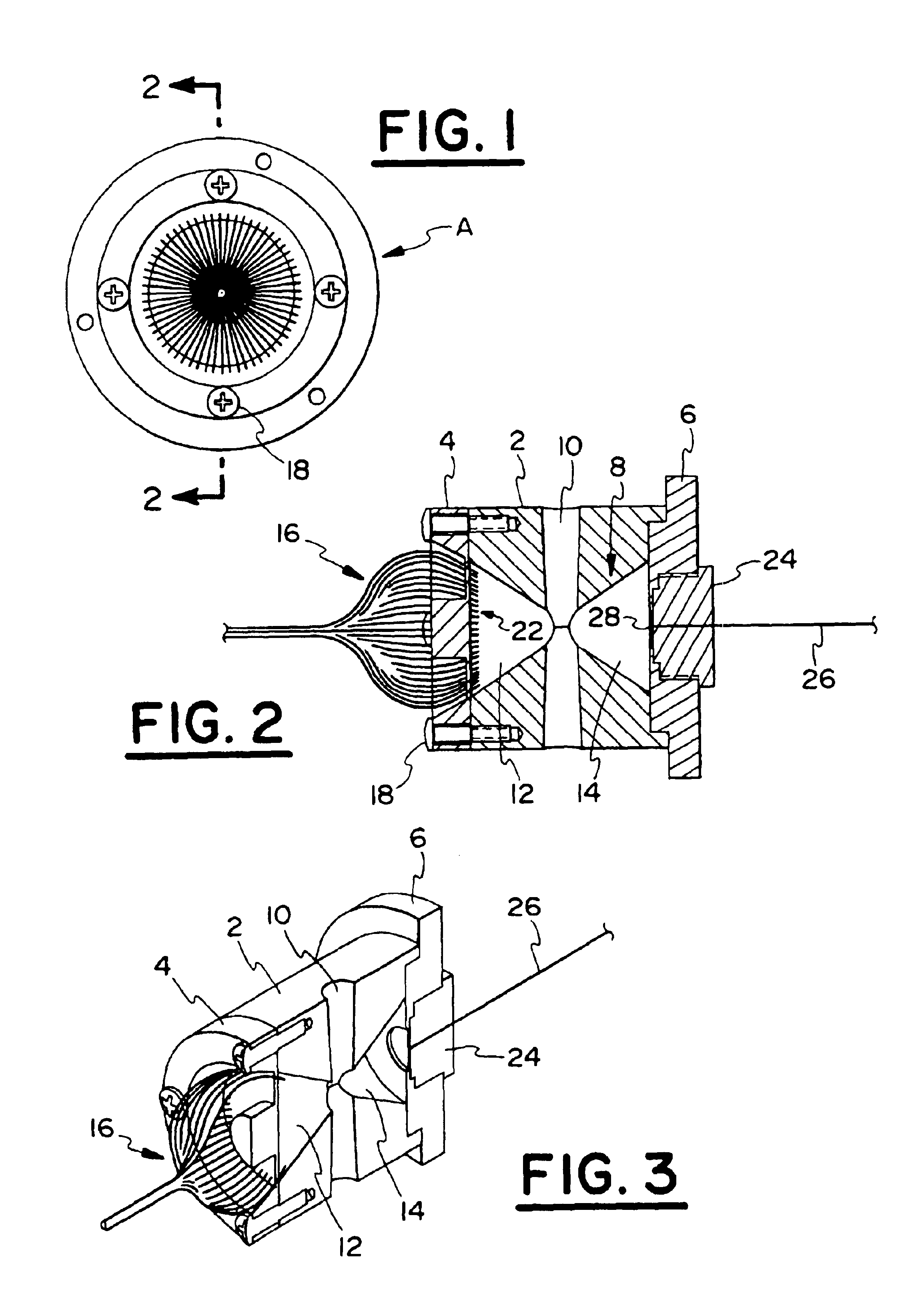
Referring to FIGS. 1 to 3, an analyzing probe A is illustrated in one of many possible configurations. The details of the analyzing probe A are further shown in FIGS. 2 and 3. Referring to FIGS. 2 and 3, the analyzing probe A includes a body portion 2, a first end cap 4 and a second end cap 6. Preferably, the analyzing probe A has a substantially tubular housing. "Tubular" as used herein is defined a follows: a member having the form of a tube with a cross-section of any shape including but not limited circular, elliptical, square, rectangular, hexagonal, triangular, and other polygons. The body portion 2 includes a scattering chamber 8 and a ...


PUM

PropertyMeasurementUnit
angleaaaaaaaaaa
angleaaaaaaaaaa
angleaaaaaaaaaa

Abstract

An analyzing probe for insertion into numerous different environments to determine at least one characteristic of particulate matter suspended in a fluid stream of a test sample. Preferably, the analyzing probe includes a minimal amount of optical elements such as lenses that are subjected to the conditions of the environment of the fluid stream to be tested. Further, the analyzing probe is preferably designed so that it can be readily manufactured, operated and installed by relatively unskilled laborers.

Description

The present invention is directed to devices and processes used to detect particles in a fluid (i.e., liquid or gas) stream. More specifically, a fluid stream to be tested is subjected to electromagnetic radiation at a sensing region. Particles in the fluid stream cause the electromagnetic radiation to scatter. The electromagnetic radiation affected by the particles in the fluid stream being tested is processed to identify characteristics of the particles including but not limited to particle size, type, distribution and / or concentration.Various devices have been used to test fluid streams to determine characteristics of particles in the fluid stream including particle size, type, distribution or concentration. These devices typically include a light source for generating electromagnetic radiation with a particular wavelength and an optical coupler for transmitting the light to a sensing region. The light illuminating the fluid stream is scattered by the particles suspended in the f...

Claims


Application Information

Patent Timeline
Patent Type & Authority Patents(United States)
IPC IPC(8): G01N15/02
CPCG01N15/0205
Inventor VIJAYAKUMAR, RAJAGOPALMASSET, SYLVAIN DOMINIQUE
Owner HAMILTON ASSOCS
Why Eureka
Try Eureka