Vibration dampening laminate

a technology of vibration dampening and laminate, which is applied in the direction of flooring, ceilings, synthetic resin layered products, etc., can solve the problem that such techniques need to be lightweight and not overly expensive, and achieve the effect of reducing the need for vibration dampening

Inactive Publication Date: 2004-09-14
INT AUTOMOTIVE COMPONENTS GRP NORTH AMERICA INC
View PDF40 Cites 112 Cited by
  • Summary
  • Abstract
  • Description
  • Claims
  • Application Information

AI Technical Summary

Problems solved by technology

Moreover, the need for such techniques to be lightweig

Method used


Image

  • Vibration dampening laminate
  • Vibration dampening laminate
  • Vibration dampening laminate

Examples


Embodiment Construction

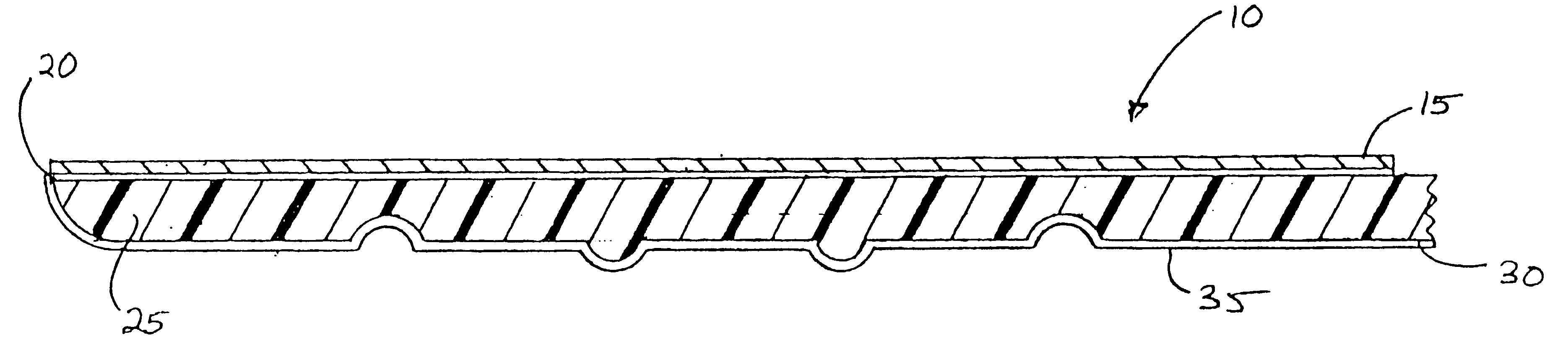
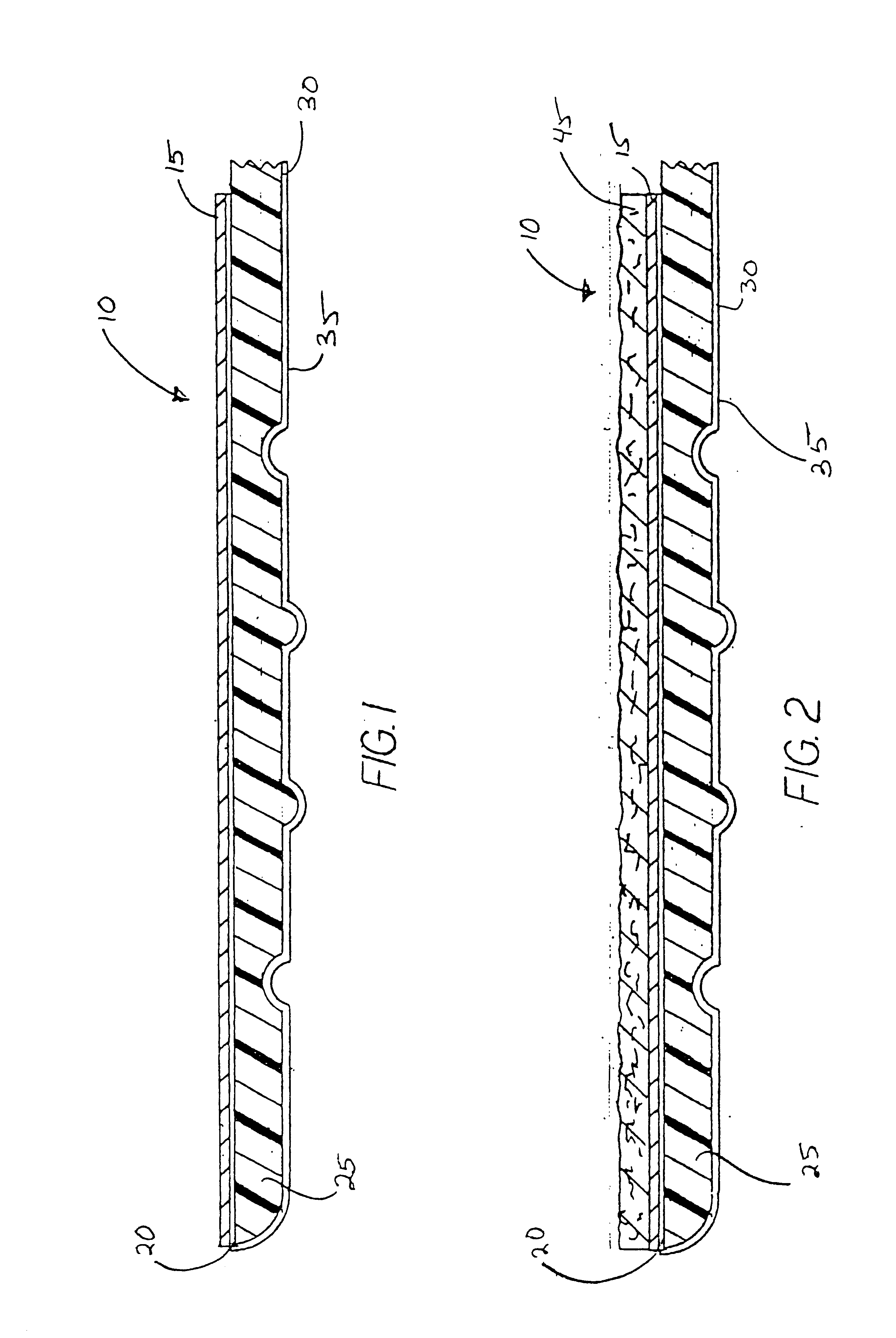
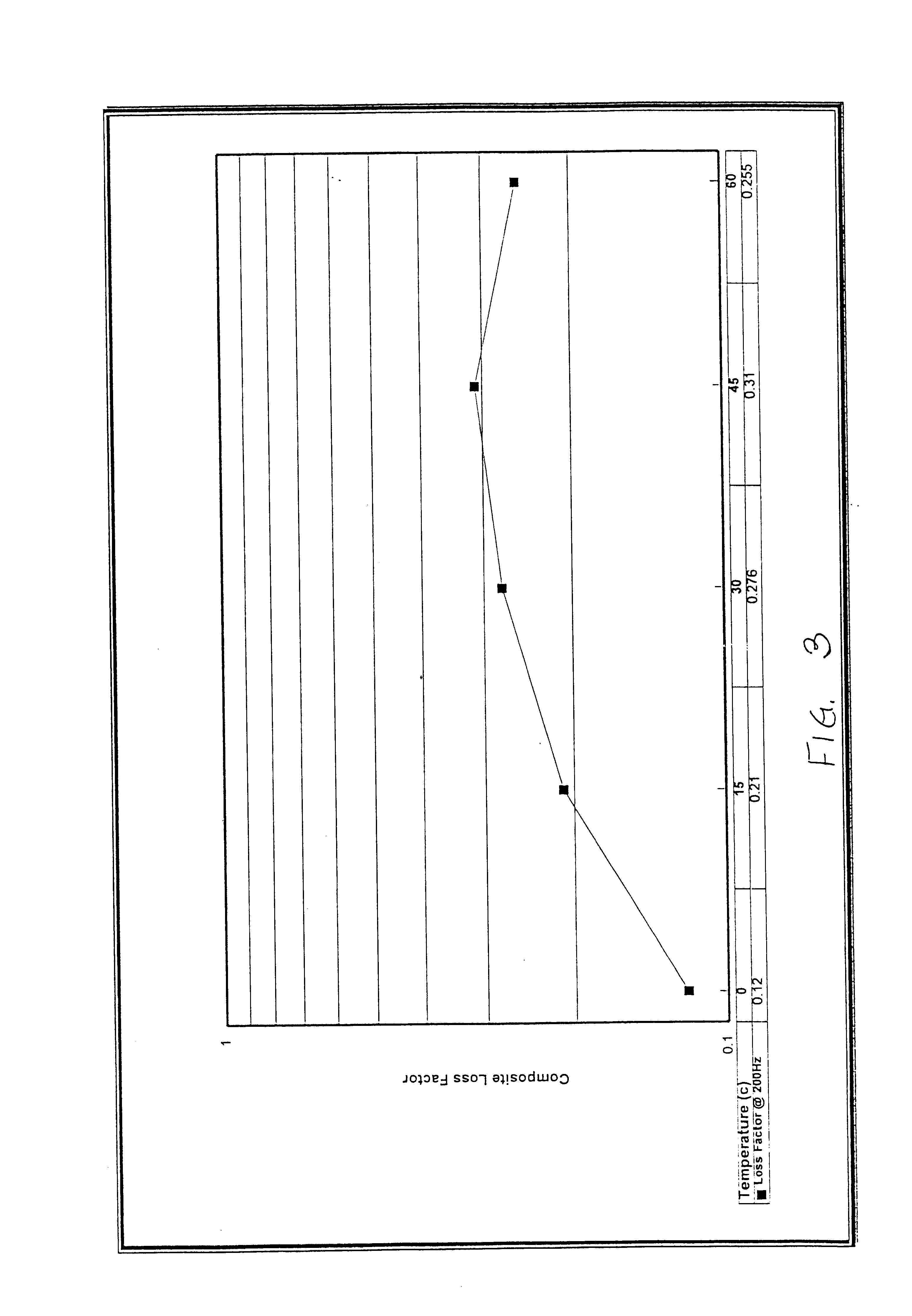
laminate comprising a 0.002 inch thick A. J. Oster aluminum foil, 0.006 inch thick Air Products 1625 acrylic viscoelastic layer, a 0.5 inch thick Foamex International polyurethane foam, a 0.006 inch thick Air Products 1625 acrylic to pressure sensitive layer and a 0.002 inch Fox River Associates release layer is provided. An ASTM E-756 Obert Beam measurement is made at various temperatures as shown in FIG. 3. The vibration dampening laminate has improved dampening properties as compared to conventional means for dampening.

While various embodiments have been disclosed and described herein, it will be appreciated that various changes and modifications can be made by those skilled in the art without departing from the true spirit and scope of the invention, as defined in the following claims.


PUM

PropertyMeasurementUnit
Pressureaaaaaaaaaa
Lengthaaaaaaaaaa
Lengthaaaaaaaaaa

Abstract

The present invention provides a vibration dampening laminate that is lightweight and has superior sound insulation and vibration dampening properties. The vibration dampening laminate comprises a constraining layer, a viscoelastic adhesive layer, a foam spacing layer and a pressure sensitive adhesive layer including a release layer. The pressure sensitive adhesive layer and release layer are contoured to fit a profile of the article being soundproofed and vibration dampened.

Description

FIELD AND BACKGROUND OF THE INVENTIONThe present invention relates to a vibration dampening laminate, and particularly a vibration dampening laminate for use in a vehicle interior.Soundproofing in vehicles, particularly consumer automobiles and trucks, is a primary concern of automakers inasmuch as "quiet" cars have become more and more popular. Conventionally, sound insulation pads are placed on surfaces of the bodywork, for example, on the floor, in the roof, on the fire wall and the like. The intent of the insulation pad is to deaden sounds and lessen vibration that are caused by movement of the vehicle, engine operation and any moving parts.In general, soundproofing can be broken down into sound insulation, sound absorption, vibration dampening and vibration insulation. Sound insulation is typically accomplished by intercepting sound waves on the way of their transmission so that a transmitted sound level is made smaller than an initial sound level. Materials capable of reducing...

Claims


Application Information

Patent Timeline
IPC IPC(8): B32B5/18B60R13/02B60R13/08G10K11/168G10K11/00G10K11/162
CPCB32B5/18B60R13/02B60R13/0815B60R13/083G10K11/168A47L15/4246Y10T428/1476Y10T428/2839Y10T428/2891Y10T428/14Y10T428/12431Y10T428/28Y10T428/2804Y10T428/12438A47L15/4255A47L15/4209Y10T428/249982Y10T428/23979Y10T442/654Y10T442/3415Y10T442/3325Y10T428/249958Y10T428/249992Y10T428/249987Y10T442/647Y10T428/249985Y10T428/249991Y10T442/3382Y10T428/249953Y10T442/15Y10T442/656B32B2266/0278B32B7/12B32B2605/003B32B2307/546B32B2311/24B32B2307/56
Inventor TODD, JOHNBOYD, ROBERT S.CARE, MELVYN J.
Owner INT AUTOMOTIVE COMPONENTS GRP NORTH AMERICA INC
Why Eureka
Try Eureka