Device for conveying and checking containers, in particular preforms

a technology for conveying containers and containers, applied in the field of preforms, can solve the problems of affecting the production cycle of the entire plant, increasing production times, and complicating the plant layout, so as to avoid damage and superfluous transfers

Inactive Publication Date: 2004-10-26
LANFRANCHI LINO
View PDF10 Cites 63 Cited by
  • Summary
  • Abstract
  • Description
  • Claims
  • Application Information

AI Technical Summary

Benefits of technology

The aim of the present invention is, therefore, to overcome the above-mentioned disadvantages by providing a device for checking containers, in particular preforms, which picks up the preforms arranged in rows and transfers them to successive stations, in particular to the forming station, avoiding any damage and superfluous transfers and rearrangement of the preforms.
Another aim of the present invention is to provide a device for checking preforms which allows adaptation between the forming station intermittent operation and the continuous operation of the plant downstream of the forming station.

Problems solved by technology

Firstly, the preforms moulded in rows inside the mould are tipped loose onto the conveyor belt.
This procedure involves the use of intermediate devices between the forming station and the blowing station, which increase production times and complicate plant layout.
Secondly, during the stage in which they are tipped onto the conveyor, the preforms are subject to impacts and damage which may compromise the good condition of the final bottle and, as a result, give rise to rejects which affect the production cycle of the entire plant.

Method used


Image

  • Device for conveying and checking containers, in particular preforms
  • Device for conveying and checking containers, in particular preforms

Examples


Embodiment Construction

.

This and other characteristics are more clearly illustrated in the detailed description which follows, with reference to the accompanying drawing, which illustrate a preferred embodiment without limiting the scope of application, and in which:

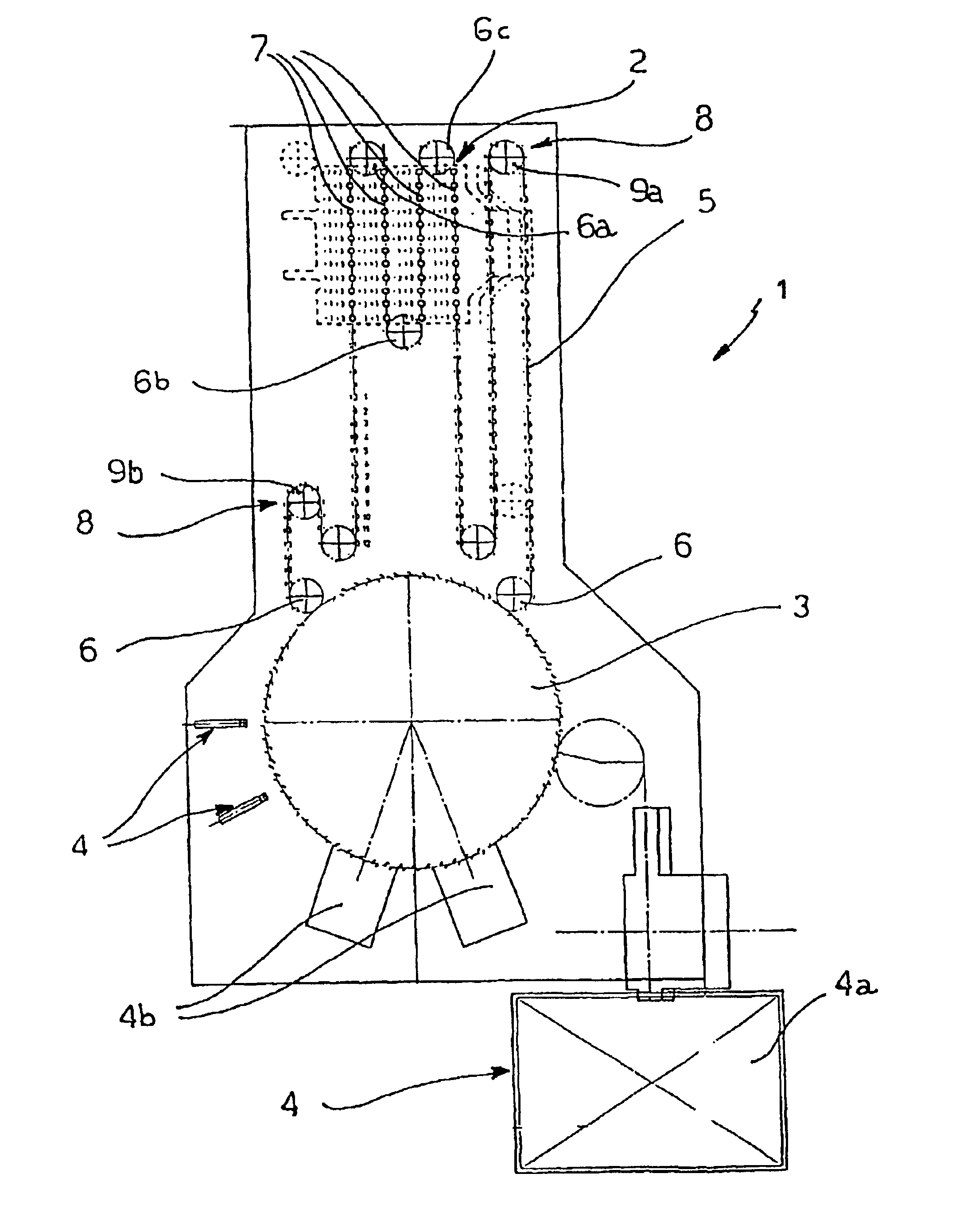
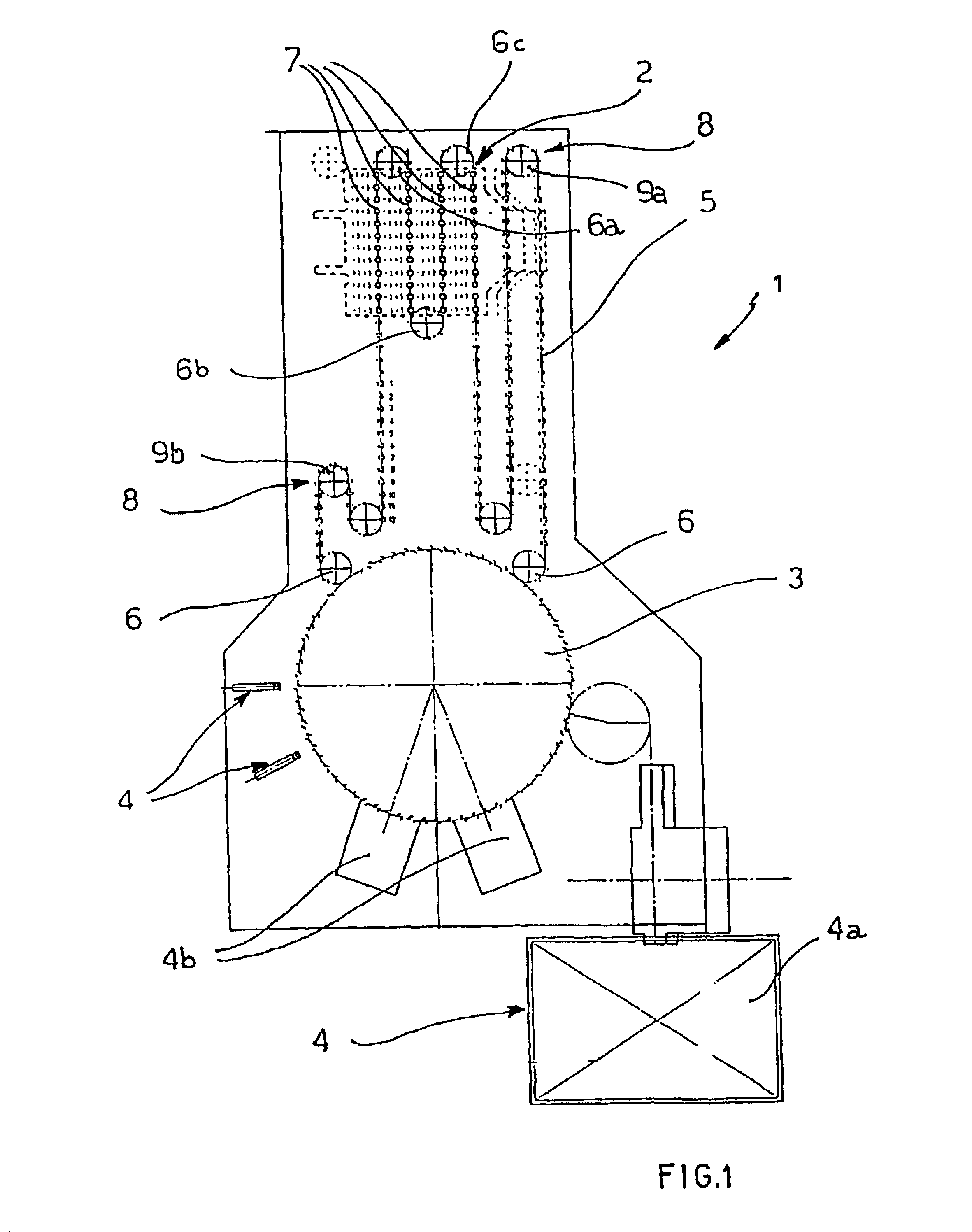
FIG. 1 is a top view of a device made in accordance with the present invention.

With reference to the accompanying drawing, the numeral 1 indicates as a whole a device for checking containers, in particular preforms.

The preforms are made by moulding in a forming station which is not illustrated, being of the substantially known type. The forming station has a mould in which the preforms are made in a plurality of rows. The preforms are also unloaded from the mould with the mouth facing downwards.

The forming station has alternating operation, since the preforms are unloaded from the mould one row at a time, whilst the forming stage is completed on the other rows. The figure illustrates a diagram of a possible layout of the device 1 in which the ...


PUM

PropertyMeasurementUnit
lengthaaaaaaaaaa
diameteraaaaaaaaaa
shapeaaaaaaaaaa

Abstract

A device (1) for conveying and checking containers, in particular preforms, comprises an infeed and accumulation section (2) for containers arriving from a forming station and a carrousel (3) located downstream of the infeed and accumulation section (2) in the direction of feed of the containers, to feed the containers through a sequence of checking stations (4) disposed in the periphery of carrousel (3). The infeed section is intermittently supplied with containers by the forming station while the carrousel (3) turns continuously. An endless chain (5) extends along a path defined by driving gearwheels (6) which partially overlaps the infeed and accumulation section (2) and the circular trajectory of the carrousel (3). A first and second driving gearwheels (9a, 9b) positioned along the path followed by the endless chain (5) are mobile to compensate the variations in the length of a delivery section and a return section of the chain (5).

Description

TECHNICAL FIELD AND BACKGROUND ARTThe present invention relates to a device for checking containers, in particular preforms.The device is included in the sector of bottling systems, substantially at the start of the production line.As is known, plastic bottles for bottling are made by means of several successive processes which include, firstly, the formation of the so-called preforms and, secondly, preform blowing to obtain the finished bottle.The preforms are cylindrical containers in which the mouth, neck and threaded portion of the neck already have their final dimensions, whilst the bottle body is cylindrical and has substantially the same diameter as the neck. The preforms are then transferred to a blowing machine, in which they are inserted in a mould with the final shape and dimensions of the bottle.The preforms are formed by moulding with intermittent production, using a mould with a set of cavities arranged in rows. The mould is tilted to unload a row of preforms onto a co...

Claims


Application Information

Patent Timeline
Patent Type & Authority Patents(United States)
IPC IPC(8): B29C31/00B29C49/80B29C49/78B29C49/42B29C49/06
CPCB29C31/004B29C49/80B29C49/4205B29C49/06B65G2201/0244B29C49/42085B29C49/4238B29C2949/0715B29C49/682
Inventor LANFRANCHI, LINO
Owner LANFRANCHI LINO
Why Eureka
Try Eureka