Laser angle guide assembly for computed tomography and method for the same

a computed tomography and laser angle technology, applied in the direction of instruments, applications, person identification, etc., can solve the problems of pain to the patient, no guide for the puncturing angle, and complications to the patien

Inactive Publication Date: 2004-11-02
CHAN WING SHEUNG
View PDF21 Cites 31 Cited by
  • Summary
  • Abstract
  • Description
  • Claims
  • Application Information

AI Technical Summary

Problems solved by technology

However, there is no guide for the puncturing angle during the specimen process.
If the puncturing angle has a large deviation relative to the desired puncturing angle, this will cause pain to the patient and even to lead complications to the patient.

Method used


Image

  • Laser angle guide assembly for computed tomography and method for the same
  • Laser angle guide assembly for computed tomography and method for the same
  • Laser angle guide assembly for computed tomography and method for the same

Examples


Embodiment Construction

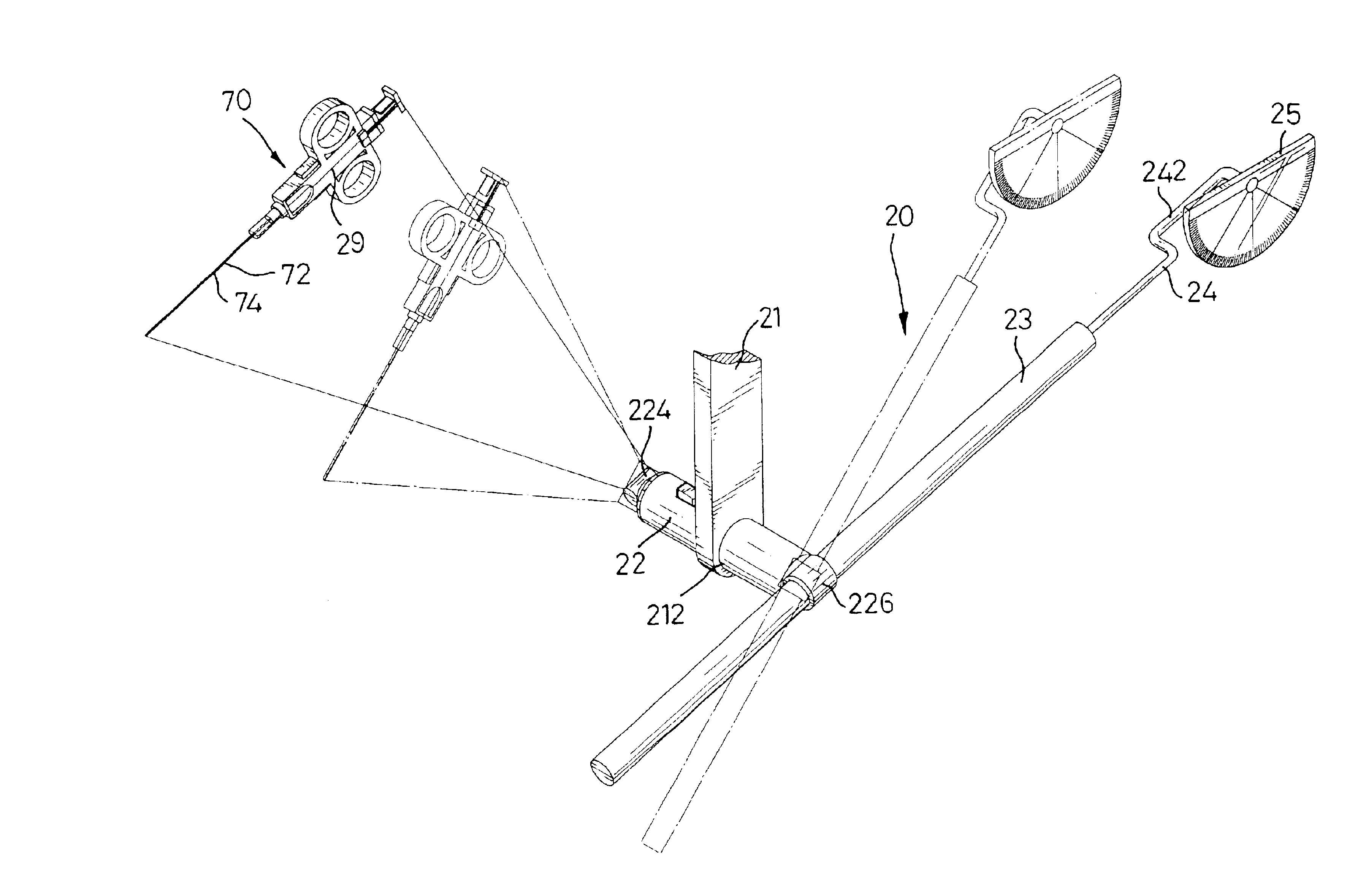
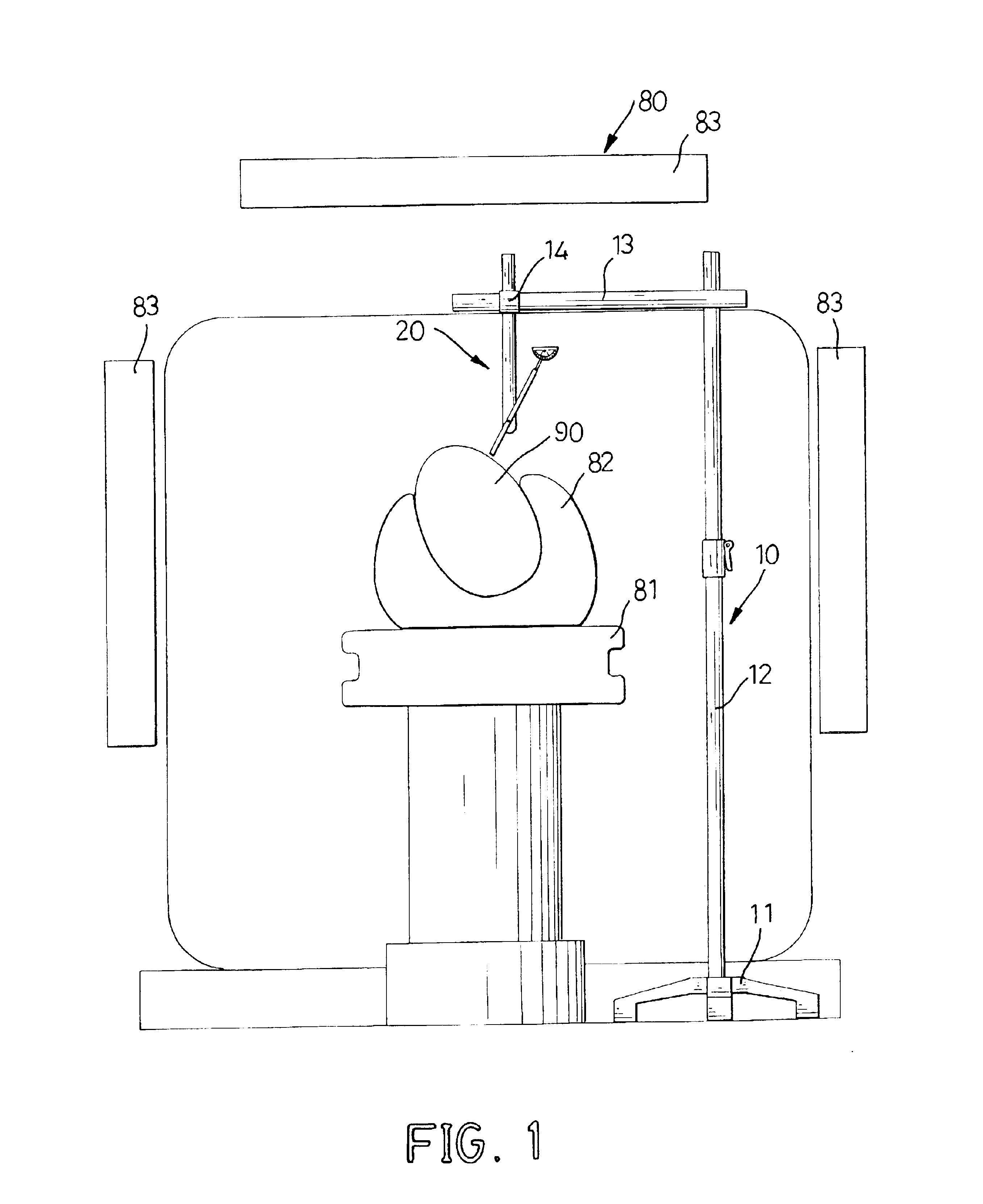
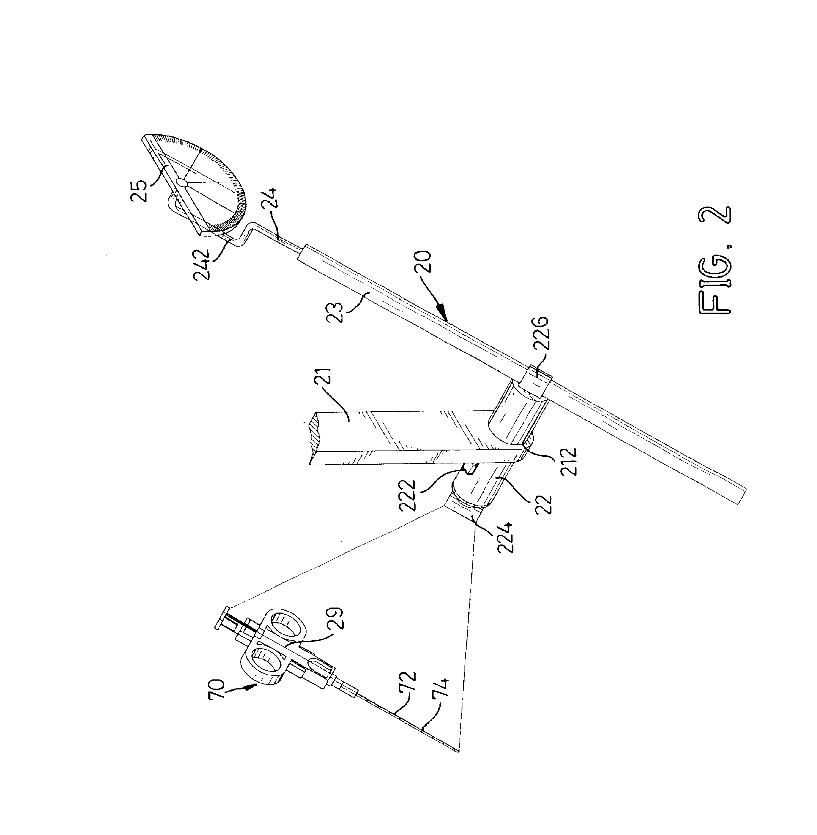
With reference to FIGS. 1 and 2, a laser angle guide assembly for a puncturing process with computed tomography (CT) in accordance with the present invention comprises a stand (10) and a laser guide (20). The stand (10) comprises a base (11), a post (12), a lateral rod (13) and an arm (21). The post (12) extends upward from the base (11). The lateral rod (13) is laterally mounted near the top end of the post (12). The arm (21) is moveably mounted on the lateral rod (13) and has a through hole (212), and the laser guide (20) is mounted in the through hole (212) in the arm (21). In practice, an annular connector (14) is mounted around the lateral rod (13), and the arm (21) is securely attached to the connector (14). Consequently, the arm (21) is moveably mounted on the lateral rod (13), and the position of the laser guide (20) is adjustable. In addition, the post (12) can be designed to be telescopic, such that the height of the laser guide (20) can also be adjusted.

The laser guide (2...


PUM


Abstract

A laser angle guide assembly has a stand and a laser guide. The laser guide is rotatably attached to the stand and has a laser pointer, a transparent column, a guiding rod, an index stick and a protractor. The laser pointer has a head for emitting a laser. The transparent column is attached to the laser pointer to transfer the laser to an index line with an inclination. The guiding bar is attached to the laser pointer. The index stick is attached to the guiding bar and has an index section with an inclination parallel to the inclination of the index line. The protractor with graduations is rotatably attached to the index stick and corresponds to the index section. Accordingly, the laser pointer will generate an index line to provide a guide to the doctor to insert the needle into the patient body at a desired angle.

Description

1. Field of the InventionThe present invention relates to a laser angle guide assembly, and more particularly to a laser angle guide assembly for computed tomography (CT) and a method for the same.2. Description of Related ArtComputed tomography is a conventional way to scan a patient for biopsy, and a specimen of tissue will be removed from the patient and be examined by a pathologist to check diseases, such as cancer. With reference to FIGS. 5 and 6, a computed tomograph (80) and a puncturing needle assembly (70) are used to remove a specimen of tissue from a patient. The computed tomograph (80) has multiple scanners (83) arranged around a patient who lies on a bed (81) and is held by a holder (82), such as a vacuum immobilization mat. A doctor will remove a specimen of tissue from the patient with the puncturing needle assembly (70) at a desired position, angle and depth determined by the computed tomograph (80). The puncturing needle assembly (70) has a needle (72) for puncturin...

Claims


Application Information

Patent Timeline
Patent Type & Authority Patents(United States)
IPC IPC(8): A61B17/34G01C15/00
CPCA61B17/3403G01C15/00Y10S33/21
Inventor CHAN, WING-SHEUNG
Owner CHAN WING SHEUNG
Why Eureka
Try Eureka