Accelerated hydrogen generation through reactive mixing of two or more fluids

a technology of reactive mixing and hydrogen generation, applied in the direction of electrochemical generators, cell components, mechanical apparatus, etc., can solve the problems of insufficient reactiveness to carry out the reaction at room temperature, unstable solutions are not suitable for fuel cell applications, and solutions lack stability in long-term storage, etc., to solve the problem of stability and reactivity, excellent long-term stability, and high specific energy

Inactive Publication Date: 2004-11-16
INTELLIGENT ENERGY LTD
View PDF12 Cites 62 Cited by
  • Summary
  • Abstract
  • Description
  • Claims
  • Application Information

AI Technical Summary

Benefits of technology

The approach taken herein of mixing two aqueous solutions in the presence of a catalyst solves the stability and reactivity issues of aqueous alkali borohydride solution simultaneously. Further, the approach taken herein of reactive mixing enables one to optimize for the variables in two opposing considerations--stability versus reactivity. The alkali borohydride solution can be formulated to provide high specific energy as well as excellent long term stability. Upon mixing with a second aqueous solution, the borohydride solution becomes "reactive" and provides an accelerated reaction rate and high percent conversion toward hydrogen evolution.

Problems solved by technology

While hydrogen gas itself is probably the most efficient source in terms of power generation, there are concerns regarding the handling of hydrogen gas.
There are two outstanding issues with the NaBH.sub.4 solution: stability and reactivity.
These solutions, however, are not sufficiently reactive to carry out the reaction at room temperature as described in Eqn. 1, even in the presence of a metal catalyst: ##STR2##
Therefore, these stable solutions are not suitable for fuel cell applications, where the operating temperature is near ambient temperature.
By lowering the strong base concentration, i.e., to 10 wt %, the solutions are very reactive in the presence of a catalyst at ambient temperature, but these solutions lack the stability in long term storage.
Over time, both the gradual loss of sodium borohydride and pressure build-up due to H.sub.2 present problems in shelf life and packaging.
Clearly, there is a delicate balance between solution stability and reactivity from a formulation perspective using the borohydride solution.

Method used


Image

  • Accelerated hydrogen generation through reactive mixing of two or more fluids
  • Accelerated hydrogen generation through reactive mixing of two or more fluids
  • Accelerated hydrogen generation through reactive mixing of two or more fluids

Examples


examples

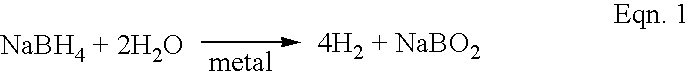
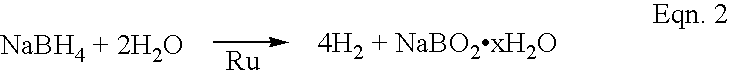
In experiments, it was found that the addition of the second aqueous solution (Solution B) to an otherwise stable NaBH.sub.4 solution (Solution A) greatly accelerated the kinetics of hydrogen evolution and the percent conversion. An example of a stable solution (Solution A) is denoted as a "30 / 15 solution". It comprised 30 wt % NaBH.sub.4, 15 wt % NaOH, and 65 wt % water. This solution has a stability in excess of 10 months under accelerated storage conditions. When this solution was mixed with ruthenium as the catalyst at 25.degree. C. and 60.degree. C., the reaction rates were 1.8 and 21.1 mL / minute, respectively, as shown in Table I below. About 0.15 wt % Ru was used as the catalyst with respect to the total weight of Solutions A and B. The Ru catalyst was prepared by chemical deposition of Ru onto a support matrix that had a high surface area (an ion exchange resin). Also shown in Table I is the result where the pH of Solution B was reduced with the addition of either a weak aci...


PUM

PropertyMeasurementUnit
temperatureaaaaaaaaaa
water-solubleaaaaaaaaaa
pHaaaaaaaaaa

Abstract

The rate of hydrogen generation in proton-exchange-membrane (PEM) fuel cells is greatly accelerated by mixing a first aqueous alkali borohydride solution with a second aqueous solution in the presence of one or more transition metal catalysts:wherein the first solution comprises (a) 5 to 50 wt % MBH4, where M is an alkali metal, (b) 5 to 40 wt % alkali hydroxide or alkaline metal hydroxide, and (c) the balance water, and wherein the second solution comprises (a) 51 to 100% water, and (b) the balance, if any, comprising at least one water-soluble additive.

Description

The present invention relates generally to fuel cells, and, more particularly, to increasing the rate of hydrogen generation to power such fuel cells.The fuel cell technology relating to hydrogen-proton exchange membrane (H.sub.2 -PEM) is of increasing interest as an alternative source of energy. A major concern is the use of pressurized H.sub.2 and O.sub.2 / air containers. H.sub.2 is difficult to liquefy, yet the means of generating it only as needed is essential for the efficient working of PEM cells.While hydrogen gas itself is probably the most efficient source in terms of power generation, there are concerns regarding the handling of hydrogen gas. While many of these concerns may not be wholly justified, nevertheless, alternative fuel sources must be found that will allay most, if not all, of such concerns.In the PEM cells, the cathode is typically Pt and the anode is also Pt. The proton exchange membrane is located between the two electrodes. On the surface of the Pt anode, on...

Claims


Application Information

Patent Timeline
Patent Type & Authority Patents(United States)
IPC IPC(8): C01B3/00C01B3/06H01M8/06H01M8/10
CPCC01B3/065H01M8/065C01B2203/066Y02E60/50Y02E60/362F17C11/005Y02E60/32Y02E60/36H01M4/92H01M8/06
Inventor TSANG, JOSEPH W.
Owner INTELLIGENT ENERGY LTD
Why Eureka
Try Eureka