
Electrical-energy meter

a technology of electrical energy meters and solid-state meters, which is applied in the direction of dynamo-electric motor meters, substation/switching arrangement details, instruments, etc., can solve the problems of increasing the overall parts count and assembly time of the meter, not reaching the extent of commercial and industrial use, and increasing the manufacturing cos

Inactive Publication Date: 2005-01-04
ELSTER ELECTRICTY LLC
View PDF22 Cites 45 Cited by
  • Summary
  • Abstract
  • Description
  • Claims
  • Application Information

AI Technical Summary

Benefits of technology

The electrical-energy meter also comprises an inner housing adapted to securely engage the circuit-board support member so the that the inner housing and the base substantially enclose the current sensor assembly and the circuit board assembly. The inner housing comprises a plurality of snaps each having a through hole formed therein. Each of the second plurality of retaining clips is adapted to substantially align with and become disposed in a respective one of the through holes in the snaps as the inner housing is mated with the circuit-board support member thereby causing the second plurality of retaining clips to securely engage the inner housing whereby the inner housing is secured to the circuit-board support member without the use of external fasteners.

Problems solved by technology

The use of solid-state electrical-energy meters in residential applications has not progressed to the extent of commercial and industrial use.
These fasteners increase the overall parts count and the assembly time of the meter, and thus raise the manufacturing cost thereof.
Thermosetting plastics are relatively hard and brittle, and thus are not well suited to withstand the impact loads that electrical-energy meters are typically exposed to during shipping and installation.
This requirement increases the manufacturing cost of the meter.
Moreover, the brittle quality of thermosetting plastics precludes the use of cost-effective design features that require resilient components.

Method used


Image

  • Electrical-energy meter
  • Electrical-energy meter
  • Electrical-energy meter

Examples


Embodiment Construction

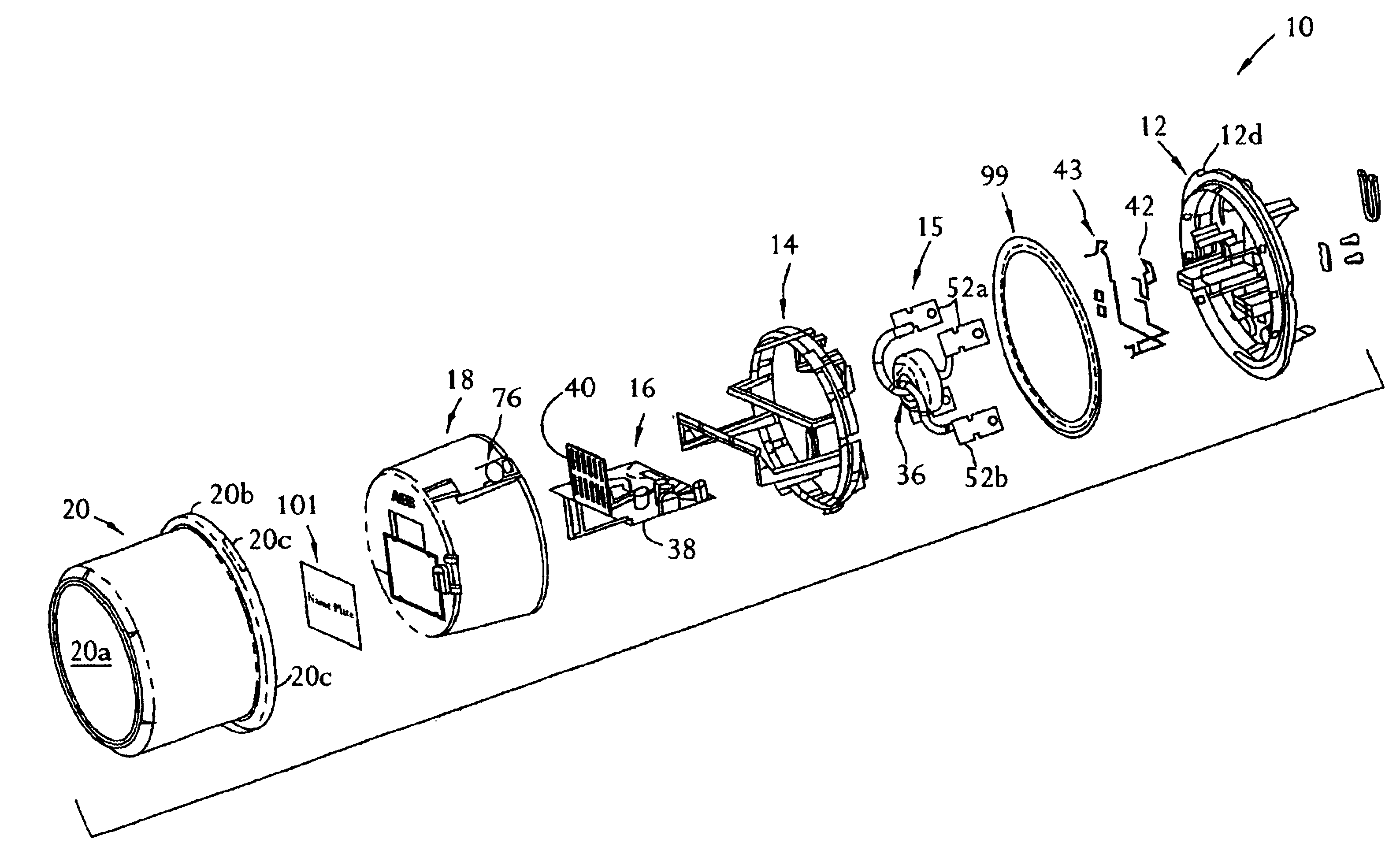
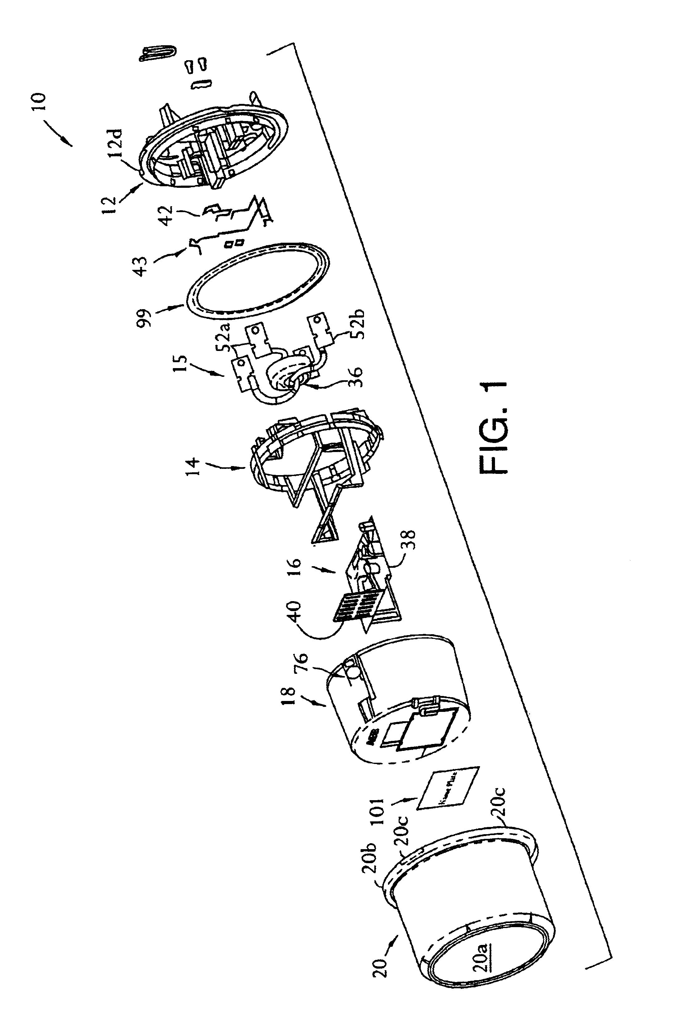
A presently-preferred embodiment of a solid-state electrical-energy meter 10 adapted for residential use is depicted in FIGS. 1 to 15B. The electrical-energy meter 10 is described in detail for exemplary purposes only, as the various features of the present invention can be incorporated into other types of electrical-energy meters, including electrical-energy meters adapted for commercial and industrial uses.

The electrical-energy meter 10 comprises a base 12, a circuit-board support member 14, a current sensor assembly 15, a circuit board assembly 16, an inner housing 18, and a cover 20.

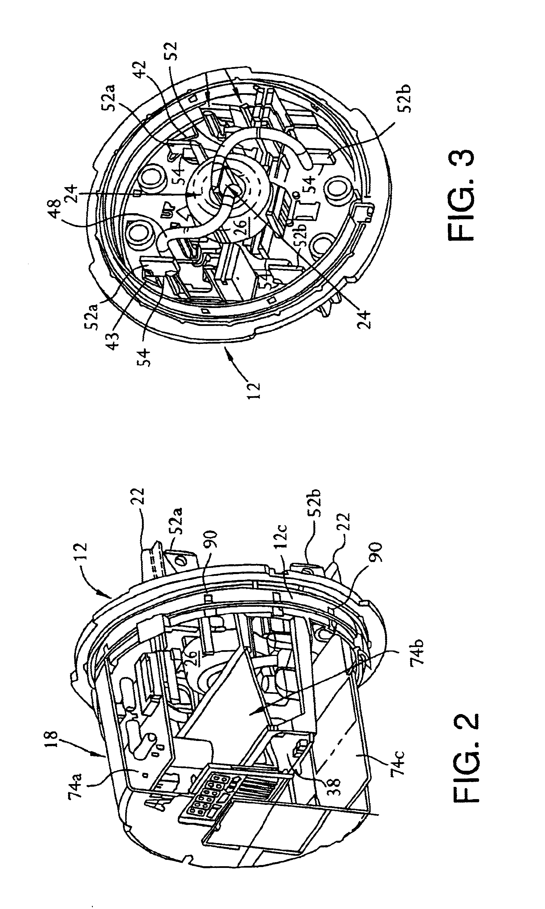
The base 12 is depicted in detail in FIGS. 3, 5, 14A, and 16. The base 12 is preferably molded from a reinforced thermoplastic material having the requisite mechanical, electrical, and thermal properties, flammability rating, UV stabilization, and resistance to common solvents such as insecticides and cleaning solutions. An example of such thermoplastic material is polyketone or PBT.

The current senso...


PUM


Abstract

A presently-preferred embodiment of an electrical-energy meter comprises a base adapted to be mounted on a supporting surface, a current sensor assembly comprising a plurality of contact blades extending through the base and adapted to electrically contact a conductor of electrical energy, and a current transformer mechanically coupled to the base and electrically coupled to the contact blades. The electrical-energy meter further comprises a circuit board assembly comprising a main circuit board electrically coupled to the current transformer and the contact blades. The electrical-energy meter also comprises a circuit-board support member comprising a rim portion fixedly coupled to the base, and a first bracket adjoining the rim portion. The first bracket has a first and a second leg each extending away from the rim portion and the base and each being adapted to securely engage the main circuit board.

Description

FIELD OF THE INVENTIONThe present invention relates to distribution systems for electrical power. More particularly, the invention relates to a solid-state meter for measuring the consumption of electrical energy in, for example, a residential dwelling.BACKGROUND OF THE INVENTIONSolid-state electrical energy meters, also referred to as “watt-hour meters,” are used on a widespread basis in commercial and industrial applications. Solid-state meters offer advantages in relation to conventional electro-mechanical electrical-energy meters. For example, solid-state electrical-energy meters can incorporate features that offer programmability, as well as flexibility in tailoring the various functions of the meter to a particular user, without substantially increasing the overall cost of the meter.The use of solid-state electrical-energy meters in residential applications has not progressed to the extent of commercial and industrial use. In particular, typical residential applications do not...

Claims


Application Information

Patent Timeline
IPC IPC(8): G01R11/00G01R11/04G01R22/00
CPCG01R22/065G01R22/00
Inventor LOY, GARRY M.
Owner ELSTER ELECTRICTY LLC
Learn More