Physically interacting with a processor-based display

a processor-based display and physical interaction technology, applied in the field of processor-based systems, can solve the problems of not being able to interact with any display screen, not being able to provide a display screen, and incurring additional expense in providing a display screen

Inactive Publication Date: 2005-01-04
INTEL CORP
View PDF9 Cites 69 Cited by
  • Summary
  • Abstract
  • Description
  • Claims
  • Application Information

AI Technical Summary

Problems solved by technology

Generally, there is no way to interact with the images generated on that system in any extensive fashion.
However, this operation requires a specialized display screen

Method used


Image

  • Physically interacting with a processor-based display
  • Physically interacting with a processor-based display
  • Physically interacting with a processor-based display

Examples


Embodiment Construction

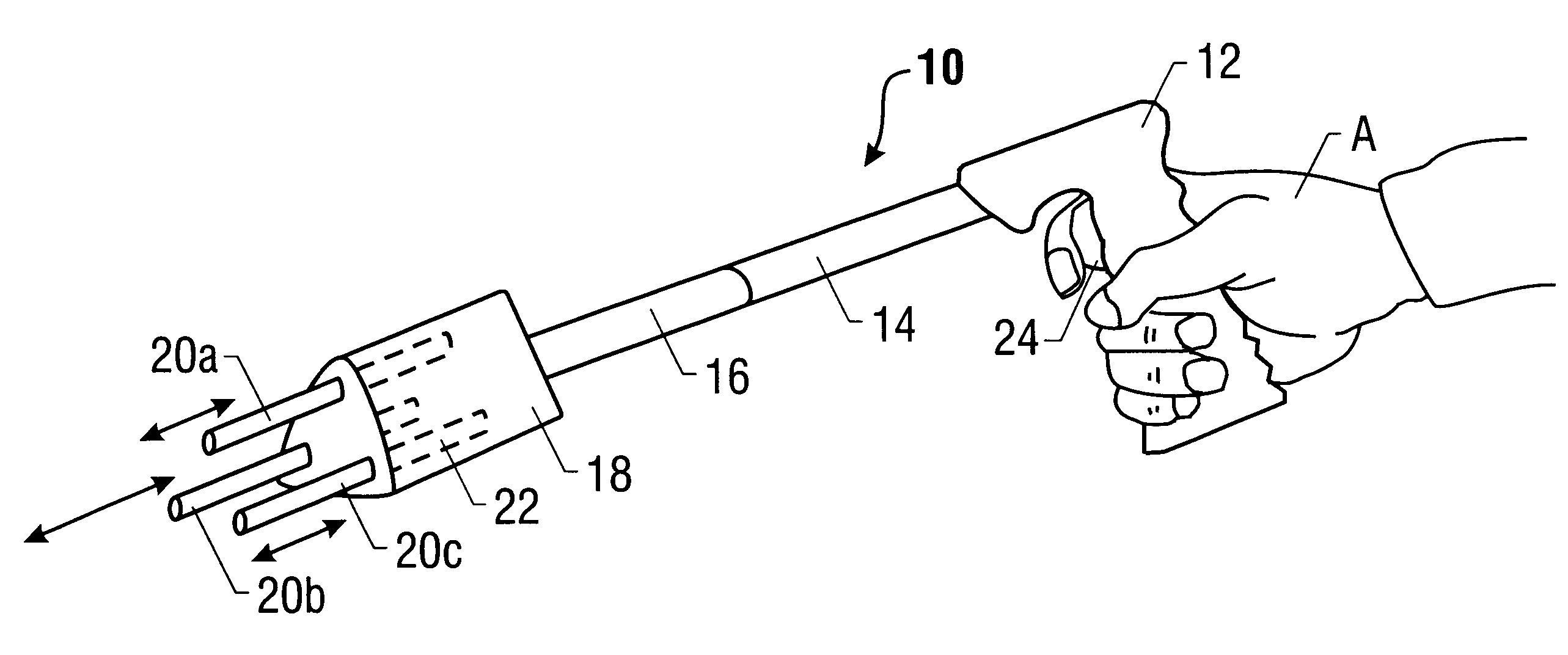
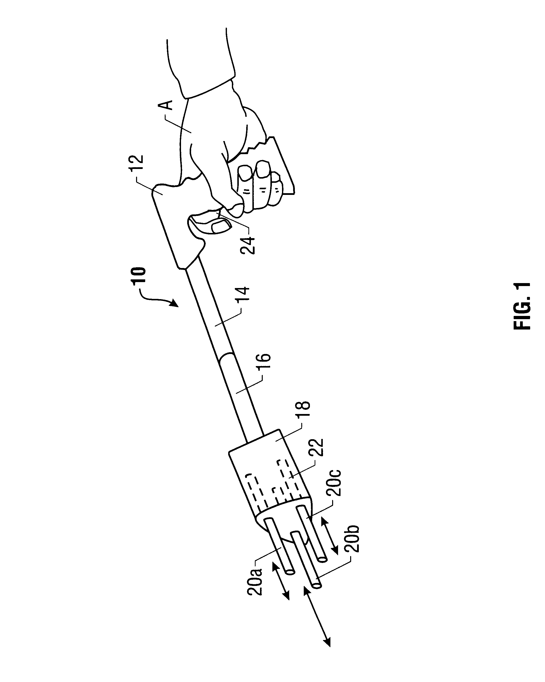
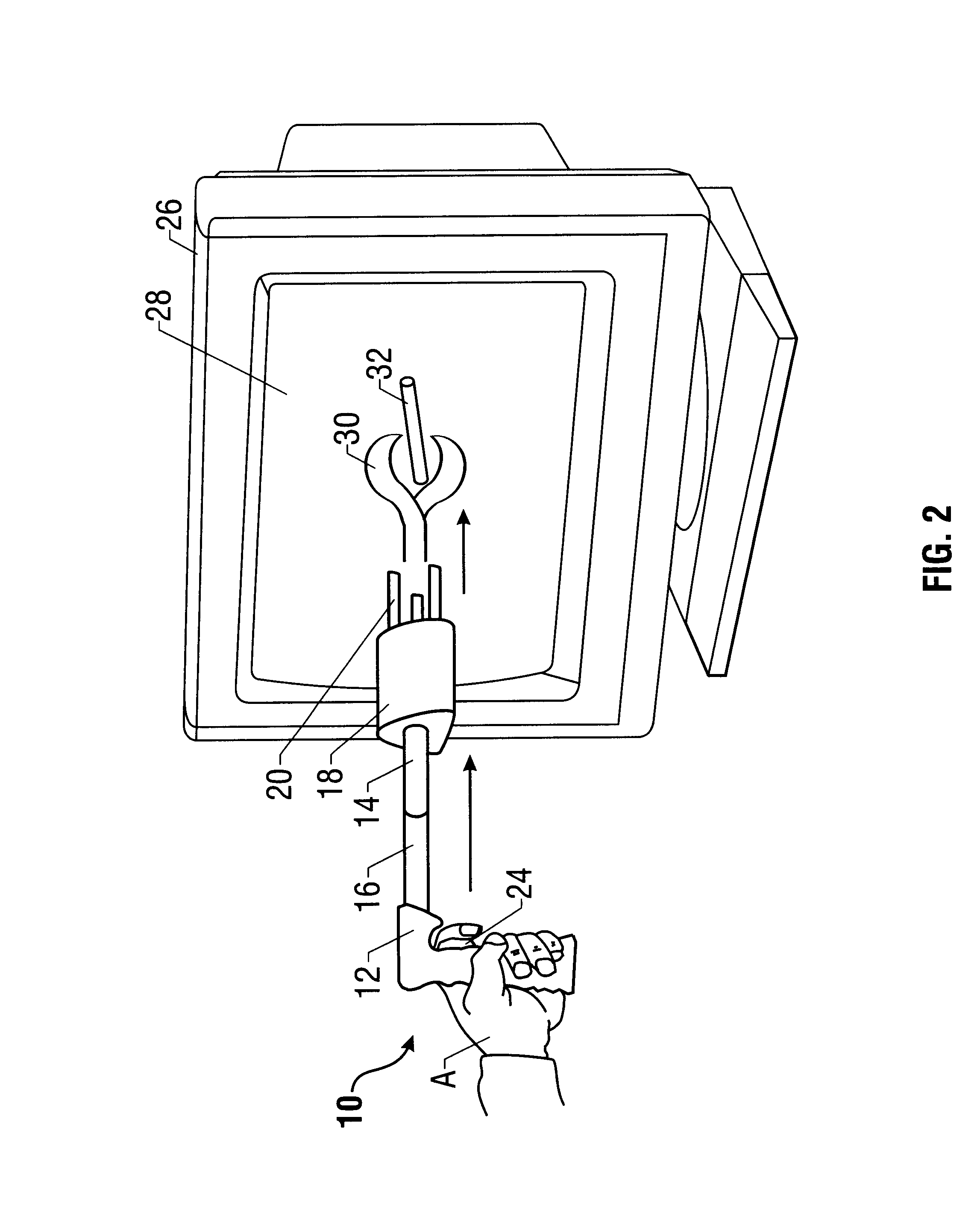
Referring to FIG. 1, an element 10 enables a user whose hand is indicated at A to interact with images being displayed on a computer display screen. In one embodiment, the element 10 includes a handle 12 that fits in the palm of the user's hand and presents a trigger 24 for operation by the user's index finger. Transversely connected to the handle 12, a telescoping shaft may include a proximal portion 14 and a distal portion 16.

The shaft portions 14 and 16 may be splined to prevent relative rotation. In one embodiment, the portions 14 and 16 are spring biased to extend apart unless constrained.

A sensor housing 18 may be coupled to the distal portion 16. The sensor housing 18 may include detectors 22 that may detect the positions of spring biased light pens 20. The spring biased light pens 20 telescope in and out of the housing 18 in the direction of the arrows. As the pens 20 extend in and out of the housing 18, the detectors 22 detect the position of each pen 20 relative to the hou...


PUM


Abstract

A physical element may be caused to appear to interact with an image displayed on a computer display screen. The position of the element with respect to the display screen may be determined automatically. The user can then manipulate the element to cause an image, which may appear to be connected to the element, to be altered. Therefore, the user gets the impression that the element is capable of interacting and altering an image displayed on the display screen.

Description

BACKGROUNDThis invention relates generally to processor-based systems.A processor-based system may include a display having a display screen. The display screen may display images generated by a processor-based system. Generally, there is no way to interact with the images generated on that system in any extensive fashion.For example touch screens are available which enable the user to touch the display screen and thereby to select an icon displayed on the screen. However, this operation requires a specialized display screen. The display screen must include a sensor which detects the presence of the user's finger and thereby correlates that presence to the selection of an appropriate icon. Thus, the interaction that is possible is a direct result of the special configuration and construction of the display screen itself. Such interaction is not possible with any display screen. Moreover, additional expense may be incurred in providing a display screen which is also sensitive to touc...

Claims


Application Information

Patent Timeline
IPC IPC(8): G06F3/033G06F3/041
CPCG06F3/0414G06F3/03542
Inventor KOIZUMI, DAVID H.
Owner INTEL CORP
Why Eureka
Try Eureka