Fastener and support leg for adjustable cross bar for bed rails and frames

a cross bar and adjustable technology, applied in the field of bed frames, can solve the problems of box spring sag bed legs to split away from the end board, etc., and achieve the effect of convenient and inexpensive fabrication

Inactive Publication Date: 2005-01-11
FREDMAN BROS COMPANY
View PDF28 Cites 24 Cited by
  • Summary
  • Abstract
  • Description
  • Claims
  • Application Information

AI Technical Summary

Benefits of technology

It is a primary object of the present invention to provide a cross bar construction, especially for full, king, California king, and queen size beds, which is adjustable in width and height, and which is easily and inexpensively fabricated at the factory.

Problems solved by technology

The side rails tend to warp, twist outwardly or deflect under the weight of the box spring and other bedding components, which causes the box spring to sag.
This especially is a problem with wider span beds and bedding, such as, queen size and king size widths, since the wider bedding is heavier as well as being wider and longer.
Slats setting on angle iron or wood rails not only push the rails downwardly, but also push the rails outwardly when weight or torquing of these rails frequently cause the bed legs to split when the slot in the legs of the beds is too close to the outside edge of the leg, or cause the bed legs to split away from the end board.
These slats are normally 1″ thick or less and create a sway in the box spring between one slat and the next, thereby weakening the frame of the box spring.

Method used


Image

  • Fastener and support leg for adjustable cross bar for bed rails and frames
  • Fastener and support leg for adjustable cross bar for bed rails and frames
  • Fastener and support leg for adjustable cross bar for bed rails and frames

Examples


Embodiment Construction

The following detailed description illustrates the invention by way of example and not by way of limitation. This description will clearly enable one skilled in the art to make and use the invention, and describes several embodiments, adaptations, variations, alternatives and uses of the invention, including what we presently believe is the best mode of carrying out the invention.

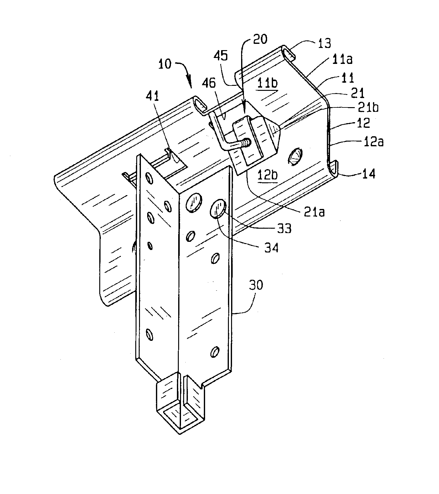
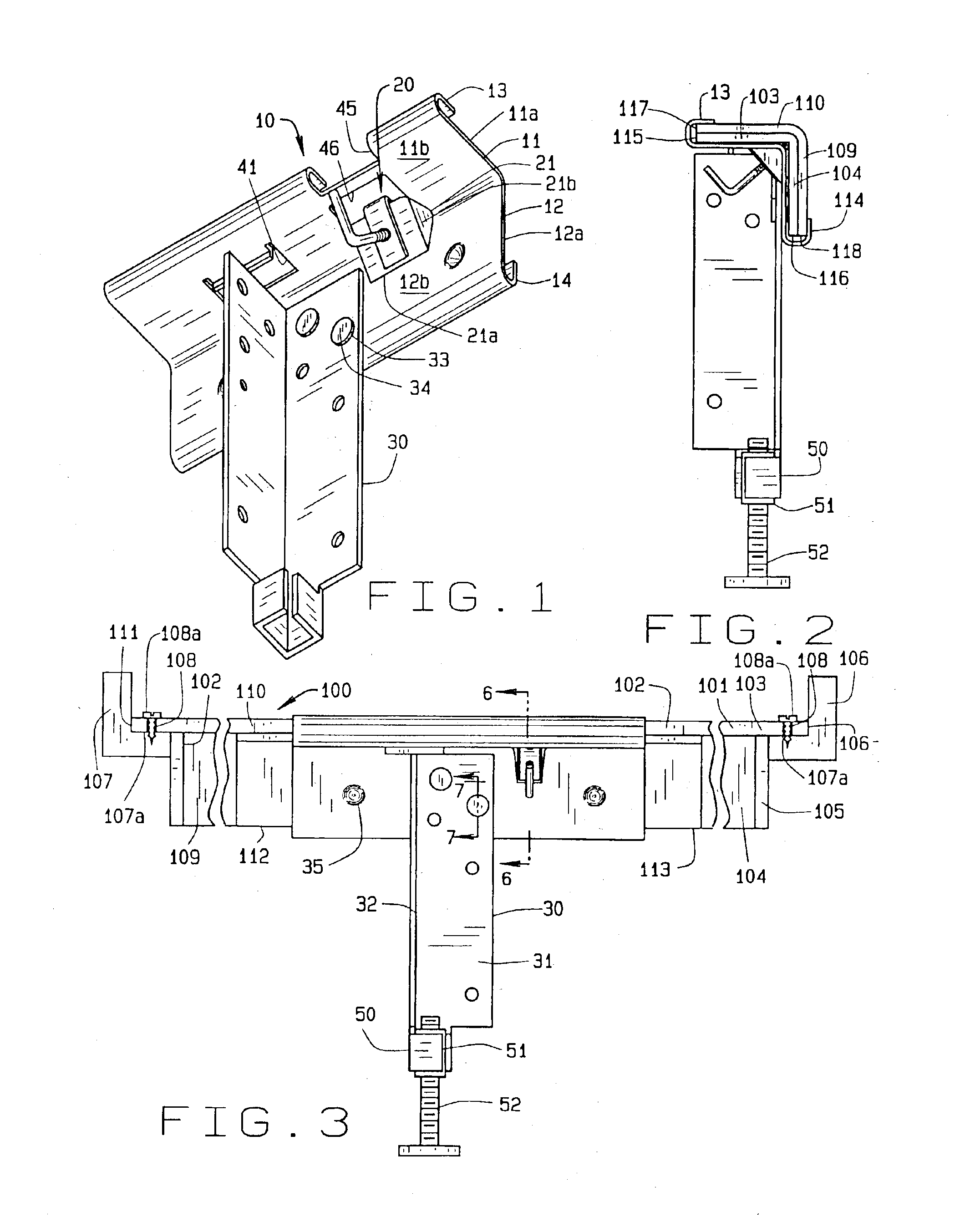
This invention is an improvement on the adjustable cross bar connector shown in detail in FIG. 4 of U.S. Pat. No. 5,203,039 and identified by numerals 20-25 of that patent and on the connector identified by the numerals 100 et. seq. in U.S. Pat. Nos. 6,209,155 and 6,397,413. The structures of U.S. Pat. Nos. 5,203,039, 5,502,852, 6,209,155 and 6,397,413 are herein incorporated by reference to the extent necessary to define background for a completion of the present disclosure.

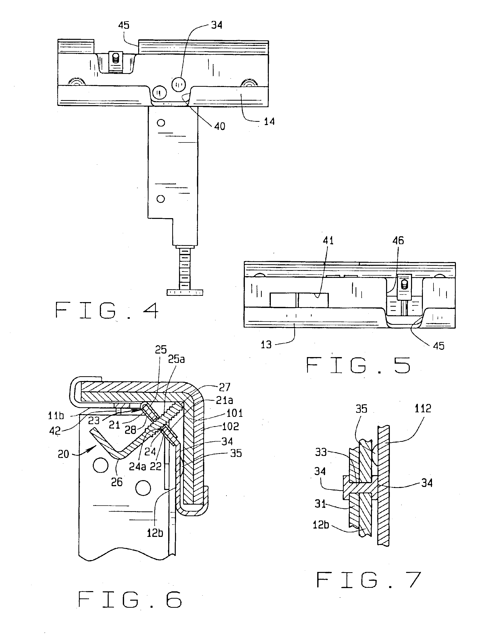
FIG. 3 shows a cross-bar 100 which comprises a main cross bar member 101 and an adjustable cross bar member 102.

The main cross bar mem...


PUM


Abstract

An adjustable locking mechanism incorporated in a bracket embracing laterially slidable first and second members, said mechanism being incorporated in the bracket and having a first element engaged with the bracket and a second element engaged with the first element and movable through both the first element and the bracket into engagement with the first member to force the first member into engagement with the second member to hold said first and second members in fixed lateral relationship to each other.

Description

CROSS-REFERENCE TO RELATED APPLICATIONSSTATEMENT REGARDING FEDERALLY SPONSORED RESEARCH OR DEVELOPMENTNot Applicable.BACKGROUND OF THE INVENTION1. Field of the InventionThis invention relates to beds and bed frames which have metal or wooden bed rails and to metal adjustable cross bars with legs for supporting the cross bars. While this invention is particularly applicable to full, queen, California king and king size beds which require legs on the cross bars to support the extra width and weight of such beds and bedding, it also is applicable to twin size beds where legs may be desired.Specifically, this invention is related to adjustable angle iron cross bars for bed rails and frames designed for use with various sized beds and to a fastener for connecting the parts of the adjustable angle iron cross bars together, which fastener has a support leg fastened thereto.2. Description of the Prior ArtConventional beds and bed rails require longitudinally spaced, transversely extending w...

Claims


Application Information

Patent Timeline
Patent Type & Authority Patents(United States)
IPC IPC(8): A47C19/00A47C19/02
CPCA47C19/024A47C19/027A47C19/025
Inventor SCHULTE, JOHN K.
Owner FREDMAN BROS COMPANY
Why Eureka
Try Eureka