Pneumatic tire having excellent steering stability
a technology of pneumatic tires and steering stability, which is applied in the field of pneumatic tires, can solve the problems of not being able to satisfy the steering stability sufficiently, and achieve the effect of improving the steering stability
- Summary
- Abstract
- Description
- Claims
- Application Information
AI Technical Summary
Benefits of technology
Problems solved by technology
Method used
Image

Examples
example 1
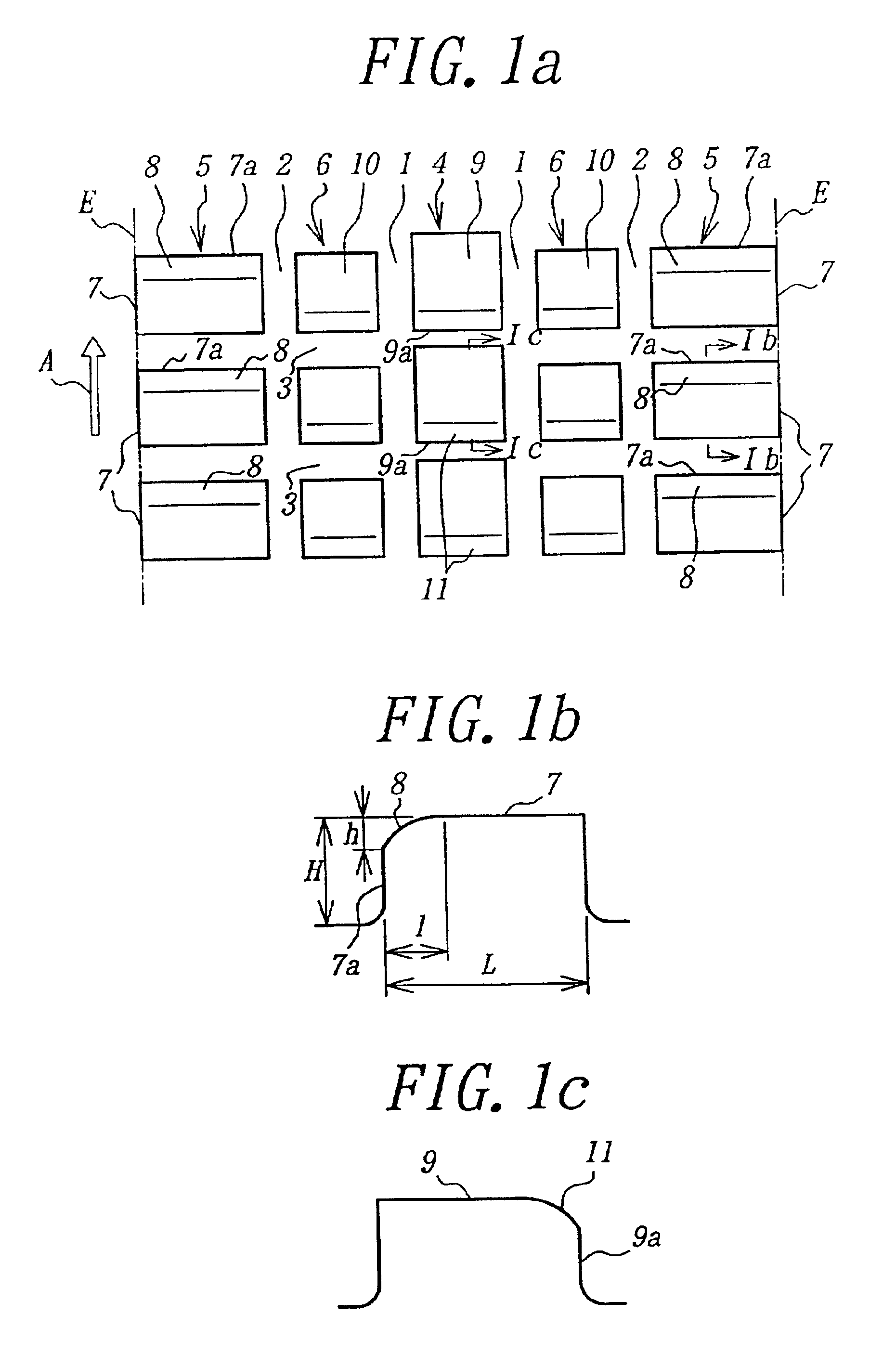
There is provided a pneumatic tire having a tire size of 195 / 60R15 88H and a tread pattern shown in FIG. 1a, wherein a belt is comprised of two cross belt layers, cords of which layers are crossed with each other at a cord angle of 20° with respect to an equator of the tire and has a width of about 150 mm, and each block has a height of 5 mm and a length in circumferential direction L of 18.9 mm, and a chamfered face formed in a shoulder block has a forming region length 1 of 6 mm and a forming region height h of 1.2 mm. This tire is mounted onto a rim of 6J and inflated under an air pressure of 220 kPa and rotated on a drum testing machine at a speed of 60 km / h under a load of 4067 N while applying a slip angle of 3° to measure a self-aligning torque.
For the comparison, there is provided a comparative tire wherein the chamfered face formed in all of the blocks is the same as formed in the center block and the middle block shown in FIG. 1. The self-aligning torque of this comparativ...
example 2
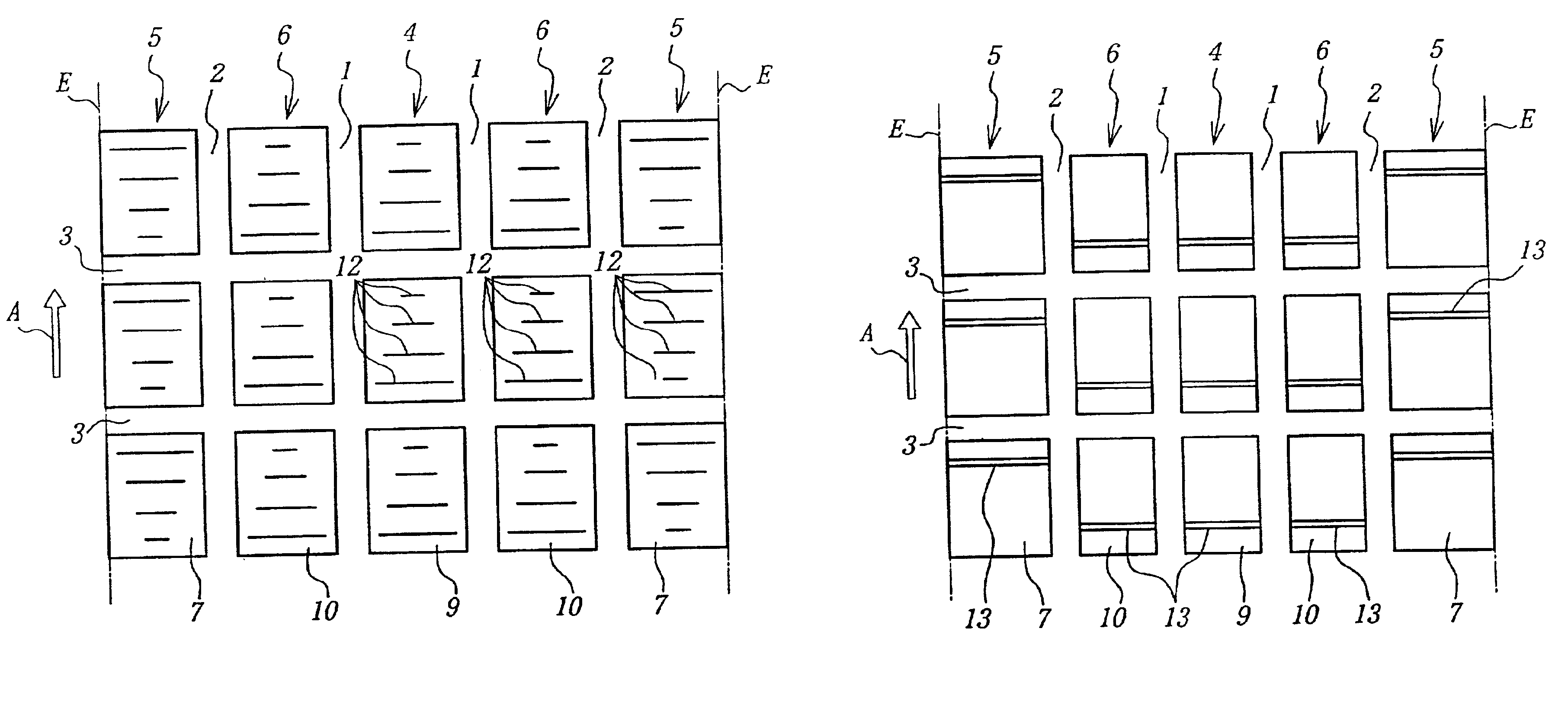
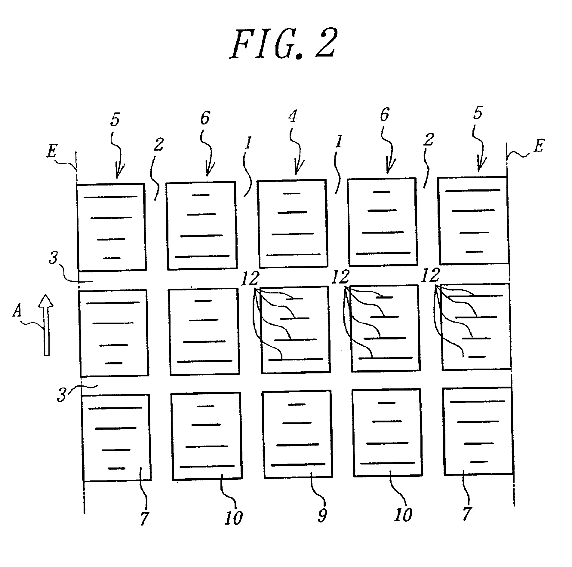
There is provided a tire having the same structure as in Example 1 except that the tire has a tread pattern shown in FIG. 2, wherein four sipes having an opening width of 0.3 mm are formed in each of all blocks and lengths of the sipes in each of shoulder blocks located at a position apart from a tread end within 0.15 times a ground contact width of a tread successively change into 20 mm, 14 mm, 8 mm and 4 mm from a leading edge of the block and lengths of the sipes formed in the other blocks successively change into 20 mm, 14 mm, 8 mm and 4 mm from a trailing edge of the block. The self-aligning torque of this tire is measured in the same manner as in Example 1.
For the comparison, there is provided a comparative tire wherein four sipes having a length of 10 mm are formed in all of the blocks.
When the self-aligning torque is represented by an index on the basis that the comparative tire is 100, the index value of the example tire is 100.5, so that the self-aligning torque can be inc...
example 3
There is provided a tire having the same structure as in Example 1 except that the tire has a tread pattern shown in FIG. 3, wherein each of all the blocks is provided with a fine groove having an opening width of 2 mm and the fine groove formed in the shoulder block is located apart from a leading edge of the block by ⅕ of a length of the block in a circumferential direction and the fine groove formed in the other blocks is located apart from a trailing edge of the block by ⅕ of a length of the block in the circumferential direction.
For the comparison, there is provided a comparative tire wherein the fine groove formed in all the blocks is located in a position corresponding to ½ of the length of the block in the circumferential direction.
When the self-aligning torque is represented by an index on the basis that the comparative tire is 100, the index value of the example tire is 101, so that the self-aligning torque can be increased by about 1%.
As mentioned above, according to the ...
PUM
 Abstract
Description
Claims
Application Information
 - R&D Engineer
- R&D Manager
- IP Professional
- Industry Leading Data Capabilities
- Powerful AI technology
- Patent DNA Extraction
Browse by: Latest US Patents, China's latest patents, Technical Efficacy Thesaurus, Application Domain, Technology Topic.
© 2024 PatSnap. All rights reserved.Legal|Privacy policy|Modern Slavery Act Transparency Statement|Sitemap