Bevel edging wheel with swarf clearance

a technology of swarf clearance and bevel edging, which is applied in the direction of gear teeth, manufacturing tools, manufacturing apparatus for gear teeth, etc., can solve the problems of manual removal of swarf from the lens, improper bevel configuration, and addition of several hand finishing steps

Inactive Publication Date: 2005-01-11
INLAND DIAMOND PRODS
View PDF12 Cites 17 Cited by
  • Summary
  • Abstract
  • Description
  • Claims
  • Application Information

AI Technical Summary

Problems solved by technology

This creates the need to manually remove the swarf from the lens.
Any swarf which is not readily removed during the grinding of the bevel edging operation, interferes with the operation and, at the very least, slows it down and

Method used


Image

  • Bevel edging wheel with swarf clearance
  • Bevel edging wheel with swarf clearance
  • Bevel edging wheel with swarf clearance

Examples


Embodiment Construction

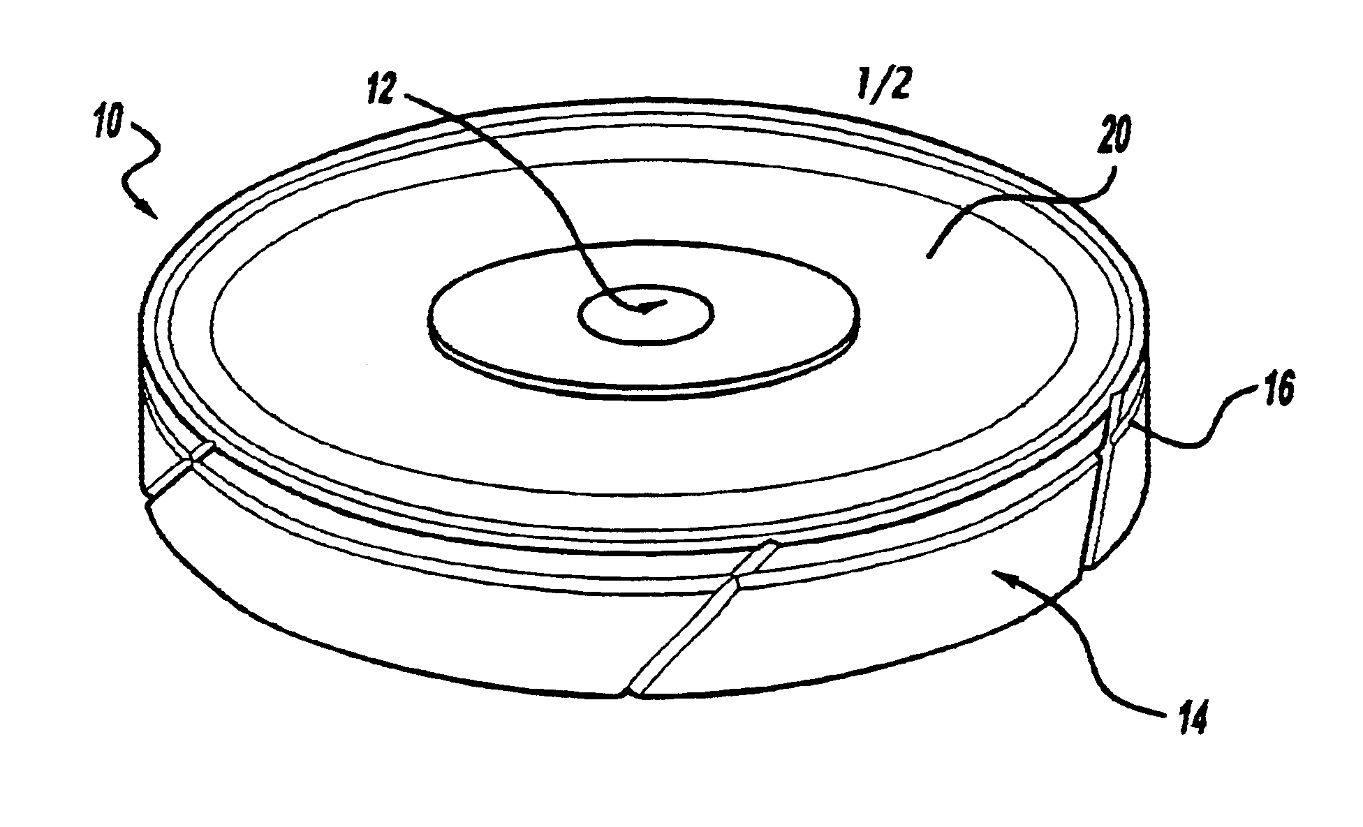
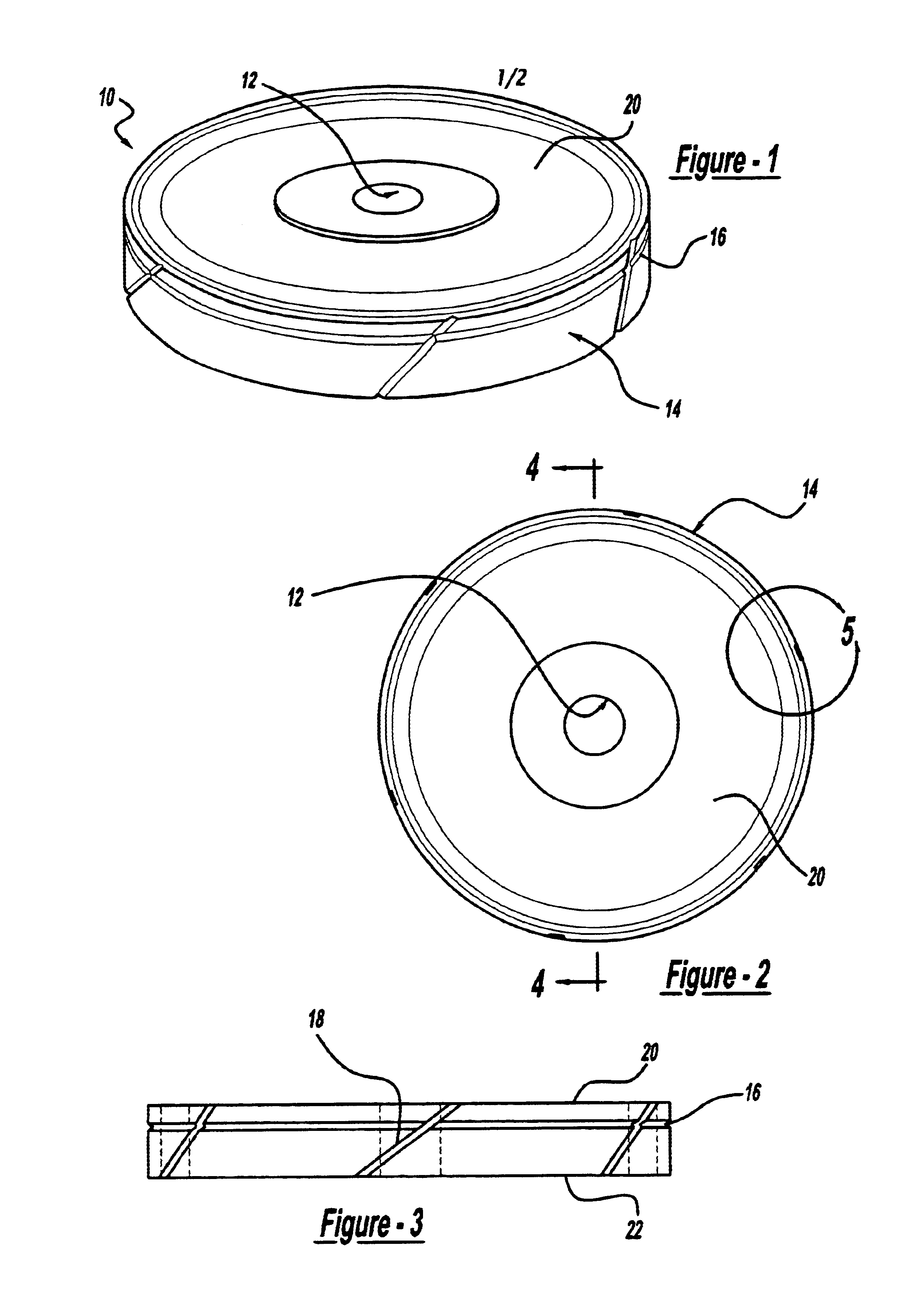
In accordance with the present invention, there is provided a rotary edging wheel generally shown at 10 for edge finishing of an optical lens. The bevel edge wheel of the present invention includes a hub portion generally indicated at 12 and an outer circumferential cutting surface generally indicated at 14.

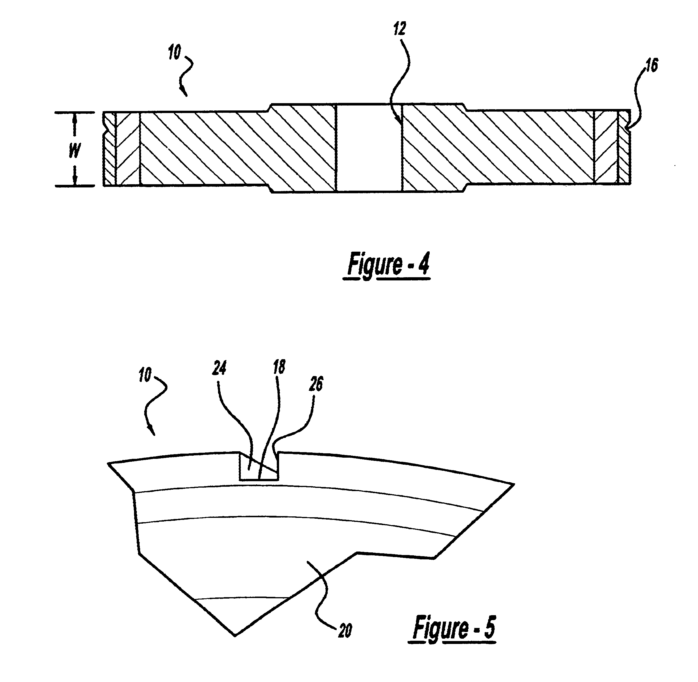
Referring now to FIGS. 2-4, an outer circumferential cutting surface includes a width W and has a circumferential groove 16 formed therein. Abrasive grit material is attached to the outer surface 14 and within the groove 16 for cutting of the lens. The wheel of the present invention includes at least one swarf clearing groove 18 which extends at least through the groove 16 to an outer planar surface of the wheel 20 or 22. The swarf clearing groove extends to the outer planar surface for removal or swarf during cutting of the lens.

In a preferred embodiment, the angle of the swarf clearing groove 18 may be 40 degrees from a side wall. Generally, the groove would be angled from abou...


PUM


Abstract

A bevel edge wheel having a swarf clearance slot across the shaping face. The slot reduces the amount of hand removal of swarf from a processed lens blank.

Description

TECHNICAL FIELDThe present invention relates to a bevel edging wheel of the type used for edging of an optical edge. More specifically, the present invention relates to a bevel edging wheel which reduces the necessary manual removal of swarf from the lens after edging of an optical lens.BACKGROUND OF THE INVENTIONOptical lenses made of polycarbonates, high index and CR39 materials are known in the art. In order to finish and make these lenses ready for fitting into a lens frame, it is necessary to bevel edge the outer periphery of the lens, to give it the proper cross-section to fit in an eye glass lens frame. Typically, this is done by a bevel edging machine, which includes a rough cut wheel for cutting out the shape and a bevel edging wheel for providing the final contour. Depending on the lens material, the grinding operation creates abrasive swarf material which requires removal in order for proper use of any type of abrasive device. Typically, the wheels have build up of swarf ...

Claims


Application Information

Patent Timeline
IPC IPC(8): B24D5/00B24D5/02B24B9/14B24B9/06
CPCB24D5/02B24B9/14
Inventor RAFFAELLI, DENNIS R.
Owner INLAND DIAMOND PRODS
Why Eureka
Try Eureka