Trigger device for chain brake

a technology of trigger device and chain brake, which is applied in the direction of chain saws, metal sawing accessories, manufacturing tools, etc., can solve the problems of large number of changes to be made on the tool, strong reactive moment, tool downwards, etc., and achieves shorter and straighter drawing, favorable motion geometry

Inactive Publication Date: 2005-01-18
HUSQVARNA AB
View PDF15 Cites 30 Cited by
  • Summary
  • Abstract
  • Description
  • Claims
  • Application Information

AI Technical Summary

Benefits of technology

The trigger device in accordance with the invention is thus essentially characterized in that the pivot of the trigger arm is located in connection to a front or a bottom side of the handle opening. Hereby the trigger arm will get a more favorable geometry of motion more corresponding to the motion of the arm at the event of kickback etc. Comparing with the known solution such a change could appear as evident. However, it means that a great number of changes have to be made on the tool to enable this location of the pivot of the tri

Problems solved by technology

However, it means that a great number of changes have to be made on the tool to enable this location of the pivot of the trigger arm.
When its rotational speed has to be stopped rapidly by a triggere

Method used


Image

  • Trigger device for chain brake
  • Trigger device for chain brake
  • Trigger device for chain brake

Examples


Embodiment Construction

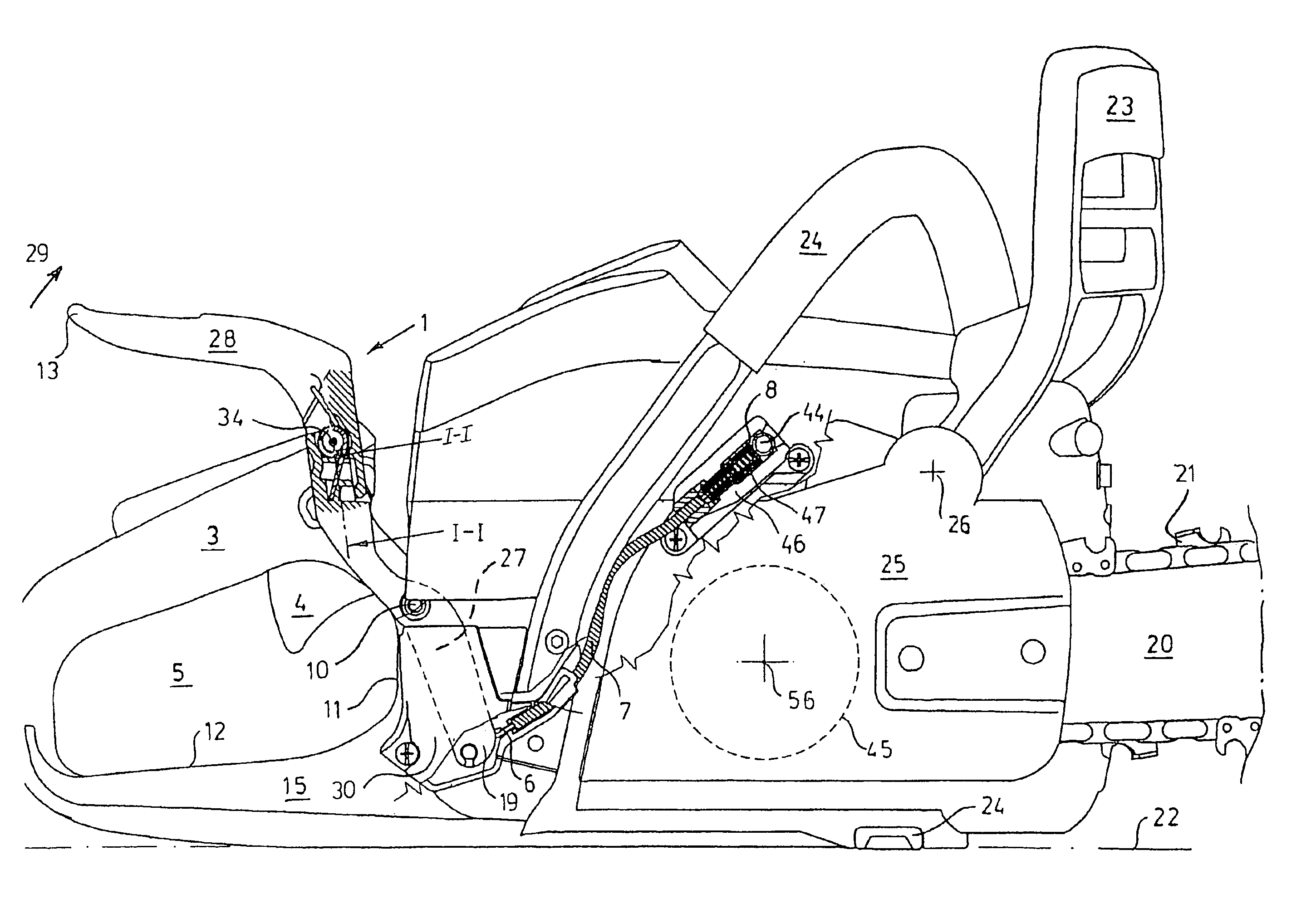
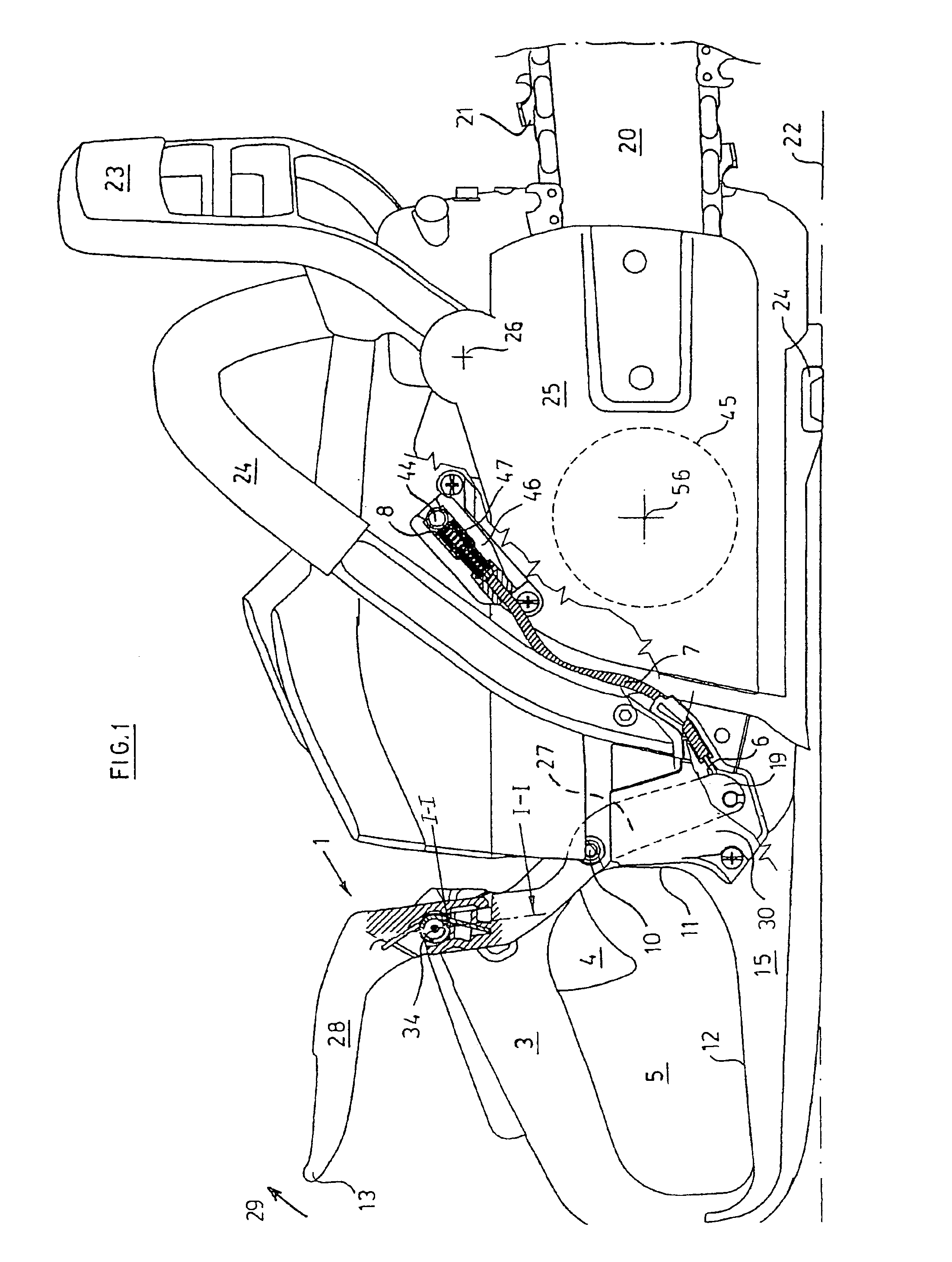
In the partly schematic FIG. 1 a chainsaw or a power saw has a saw bar 20 and a saw chain 21. In the following forwards is meant as the direction of the saw bar 20, while downwards also means downwards in the figure. For example, the saw could be placed on the ground designated by numeral reference 22. The saw has an ordinary handle frame 24 with a kickback guard 23 located in front of it. It has a rear handle 3 with a throttle control 4 and a handle opening 5 located below the handle 3. A clutch housing 25 is provided with a brake device, which will be actuated by the kickback guard 23 when this turns forwards. This is pivotably mounted at the pivot point 26. All this is conventional and will therefore not be described in closer detail. What is characteristic are the trigger arm 1 and the transfer mechanism 6, 7, 8, which actuates a brake 9, so that this stops the movement of the saw chain if the trigger arm 1 above the handle 3 is affected to create a rotation in the direction of ...


PUM

PropertyMeasurementUnit
Forceaaaaaaaaaa

Abstract

A brake triggering device with a pivotably mounted trigger arm (1) located in connection to a handheld working tool's, mainly a chain saw's (2), rear handle (3), with a throttle control (4) and a handle opening (5) located below the handle (3), so that the trigger arm (1), when the saw changes inclination in relation to the operator's forearm, e.g. at the event of kickback or fall, is actuated by the operator's hand or arm, whereby the trigger arm (1) via a transfer mechanism actuates a brake (9) so that this stops the movement of the saw chain. The pivot (10) of the trigger arm is located in connection to a front (11) or a bottom (12) side of the handle opening (5).

Description

TECHNICAL FIELDThe subject invention refers to a brake triggering device with a trigger arm located in connection to a handheld working tool's, mainly a chain saw's, rear handle with a throttle control and a handle opening located below the handle, so that the trigger arm, when the saw changes inclination in relation to the operator's forearm, e.g. at the event of kickback or fall, is actuated by the operator's hand or arm, whereby the trigger arm via a transfer mechanism actuates a brake to stop the movement of the saw chain.BACKGROUND OF THE INVENTIONWhen using a chain saw there is a risk of several kinds of severe accidents.There might be so-called kickback accidents, i.e. the saw bar with its rotating saw chain is swung up towards the saw operator. There might be fall accidents, when the user perhaps slips and falls over the saw with its rotating saw chain. In order to reduce the risk of damages at the event of kickback the chain saw is normally equipped with a chain brake that ...

Claims


Application Information

Patent Timeline
IPC IPC(8): B27B17/00B27B17/08
CPCB27B17/083
Inventor MARTINSSON, PARBJORKMAN, PETER
Owner HUSQVARNA AB
Why Eureka
Try Eureka