Pneumatic motor driving valve of screw nail gun

a screw nail gun and pneumatic motor technology, applied in the direction of nailing tools, power tools, wrenches, etc., can solve the problems of unstable output twisting force, no device for accumulating air pressure in the air driving path of the pneumatic motor, and unstable air supply to the pneumatic motor

Inactive Publication Date: 2005-01-18
DE POAN PNEUMATIC
View PDF8 Cites 43 Cited by
  • Summary
  • Abstract
  • Description
  • Claims
  • Application Information

AI Technical Summary

Benefits of technology

Accordingly, the primary object of the present invention is to provide a pneumatic motor driving valve of a screw nail gun, wherein a driving valve is disclosed for control the pneumatic motor to be operated steadily.

Problems solved by technology

Although the object of locking the screw nail is achieved, no device for accumulating air pressure in air driving path of the pneumatic motor is installed.
As a result, when the pneumatic motor is driven by air pressure, the output twisting force is unstable.
Therefore when the air supplied to the pneumatic motor will be unstable.
Thereby, the input air pressure cannot work with the downward pressing of the cylinder.
Then the operation of the screw nail gun cannot be well controlled.

Method used


Image

  • Pneumatic motor driving valve of screw nail gun
  • Pneumatic motor driving valve of screw nail gun
  • Pneumatic motor driving valve of screw nail gun

Examples


Embodiment Construction

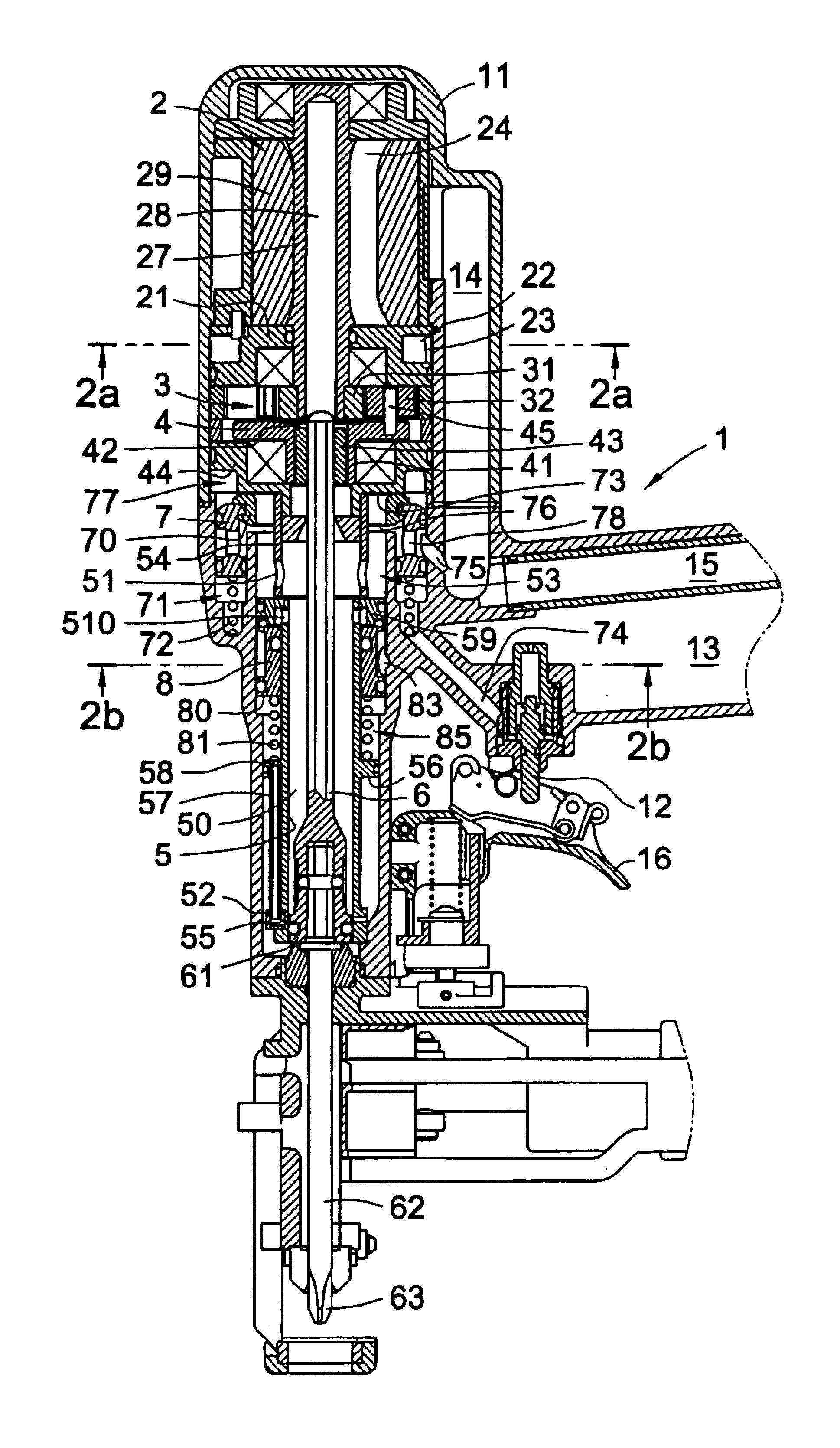
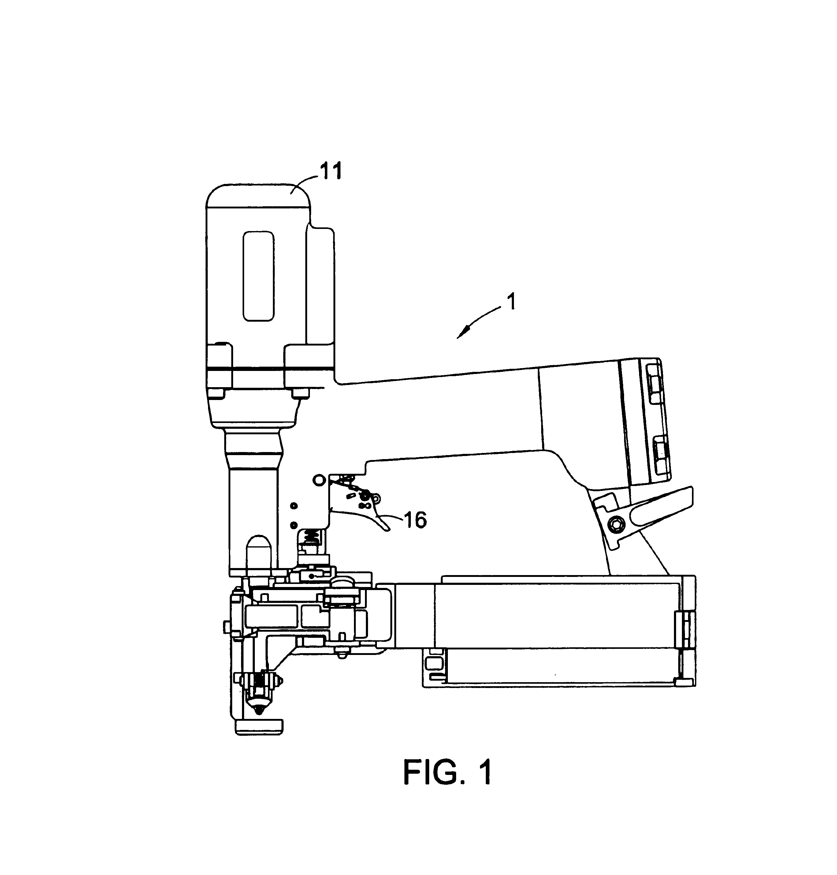
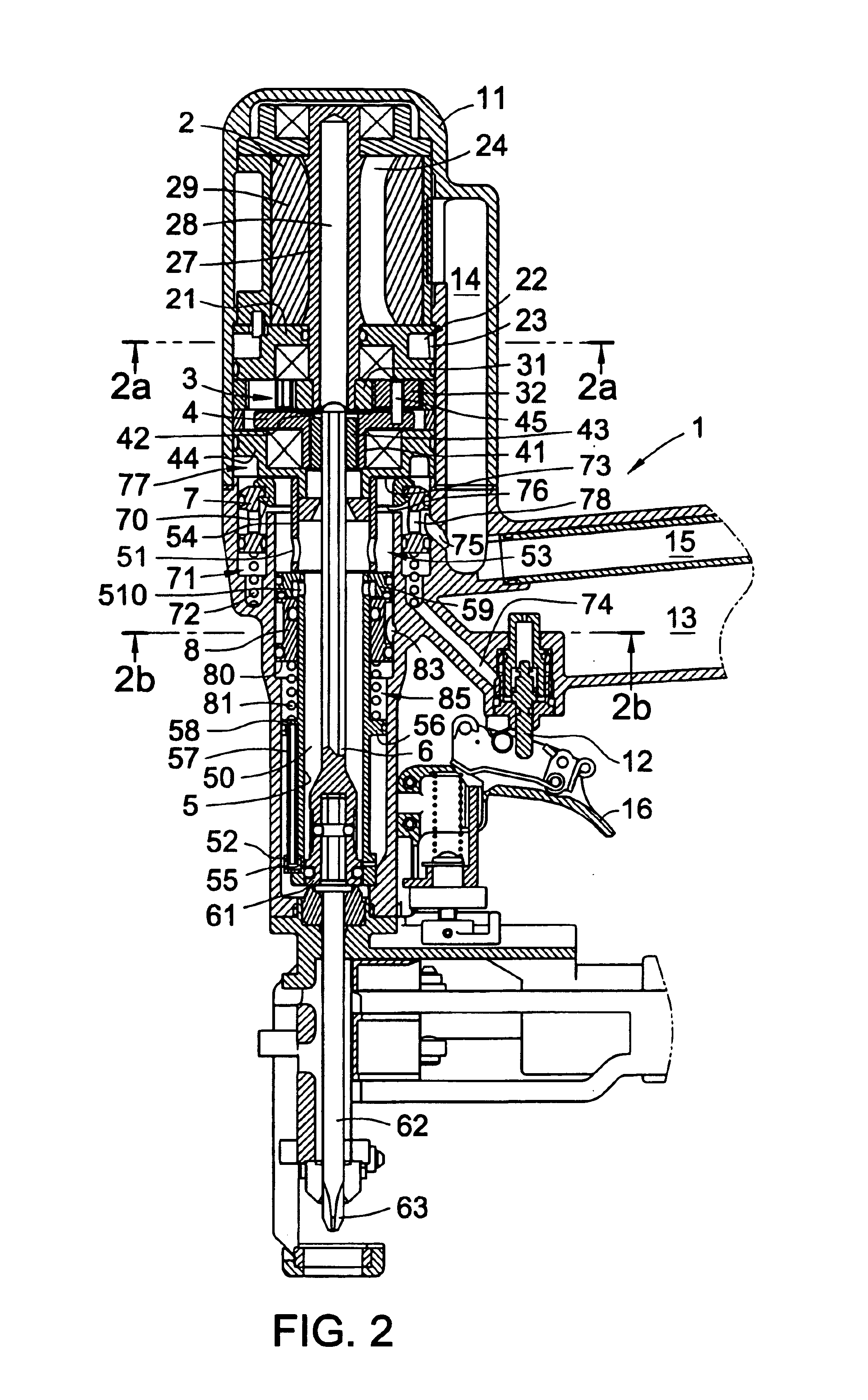
Referring to FIG. 1, the appearance of the screw nail gun 1 of the present invention is illustrated. It is illustrated from the FIG. 2 that the structure of the gun head 11 of the screw nail gun includes a pneumatic motor 2, a planet gear set 3, an output disk 4, a cylinder 5, a driving rod 6, a nail locking rod 62, a main air valve 7 and an annular control valve 8, etc.

The pneumatic motor 2 has a central spindle 27. A center of the spindle 27 has a rod groove 28. The pneumatic motor 2 has a plurality of blade receiving grooves 24 which are arranged as a radiating form for receiving blade set 29. A base plate 21 below the pneumatic motor 2 is formed with an air inlet chamber 22. One side of the air inlet chamber 22 is installed with an air inlet opening 23 (referring to FIGS. 2 and 2(a)). A portion of the air inlet chamber 22 communicated to the blade receiving groove 24 of the pneumatic motor 2 is installed with an booster opening 25. One lateral wall of the pneumatic motor 2 is fo...


PUM

PropertyMeasurementUnit
pressureaaaaaaaaaa
poweraaaaaaaaaa
twisting forceaaaaaaaaaa

Abstract

A pneumatic motor driving valve of a screw nail gun has a driving valve for control the pneumatic motor to be operated steadily. A downward pressing spring is installed around an outer wall of the cylinder of the gun body and an annular control valve is installed around the outer wall of the cylinder so that the annular control valve presses the downward pressing spring for actuating of the opening of the air inlet valve of the air inlet channel of the pneumatic motor. An annular control valve around an outer wall of the cylinder can accumulate the pressure in the gun body to a predetermined value so as to open the driving valve. Thereby, the pneumatic motor can provide a larger stable twisting force to beat and rotate a screw nail.

Description

FIELD OF THE INVENTIONThe present invention relates to screw nail gun, and particularly to a pneumatic motor driving valve of a screw nail gun which has an annular control valve on an outer wall of a cylinder of the gun body. In the present invention, valve can be opened by high pressure air and the pneumatic motor is actuate by the high pressure air.BACKGROUND OF THE INVENTIONIn one prior art about the pneumatic screw nail gun, a main air valve is installed between the pneumatic motor and the air diving path of the cylinder. The main air valve serves to control the actuation of the pneumatic motor and the cylinder in the gun body at the same time so that the nail locking rod can driving rod and descend to provide a twisting force to the screw nail so that the screw nail can be beaten into enter into the work piece. A cruciform portion at a front end of the nail locking rod is engaged to a cruciform groove in the screw nail. Thereby, the screw nail can be beaten into the work piece....

Claims


Application Information

Patent Timeline
Patent Type & Authority Patents(United States)
IPC IPC(8): B25B21/02
CPCB25B21/023
Inventor LEE, YUN-CHUNG
Owner DE POAN PNEUMATIC
Why Eureka
Try Eureka