Self-propelled load-bearing movement apparatus

a self-propelled, load-bearing technology, applied in the direction of ammunition loading, building repairs, transportation items, etc., can solve the problems of laborious current methods of performing sharp radius turns, difficult moving and relocating mobile and sectional homes, and difficult radius turns

Inactive Publication Date: 2005-01-25
JUSTICE JERRY V
View PDF11 Cites 31 Cited by
  • Summary
  • Abstract
  • Description
  • Claims
  • Application Information

AI Technical Summary

Problems solved by technology

Moving and relocating mobile and sectional homes is difficult.
The long length of the home makes maneuvering around obstacles and performing sharp radius turns arduous.
Current methods of performing sharp radius turns are laborious and include multiple realignment of the home or trailer by the transporting vehicle or winching the rear of the home or trailer across multiple sheets of soaped plywood.
Positioning the home into the correct location is also arduous due to its size and difficulty in controlling the rear of the home or trailer.
Additionally, during the transportation of the home, the weight of the home may cause one or more tires to blow.
Changing blown tires on the mobile home or trailer on a roadway can be dangerous and difficult due to the size of the home or trailer.
Similar difficulties are experienced when relocating a mobile or sectional home from one location to another.
These difficulties are experienced in maneuvering and preparing the home for transportation, maneuvering the home during transportation, and repositioning the home at the new location.

Method used


Image

  • Self-propelled load-bearing movement apparatus
  • Self-propelled load-bearing movement apparatus
  • Self-propelled load-bearing movement apparatus

Examples


Embodiment Construction

While the disclosure is susceptible to various modifications and alternative forms, specific embodiments thereof have been shown by way of example in the drawings and will herein be described in detail. It should be understood, however, that there is no intent to limit the disclosure to the particular forms disclosed, but on the contrary, the disclosure is to cover all modifications, equivalents, and alternatives falling within the spirit and scope of the disclosure as defined by the appended claims.

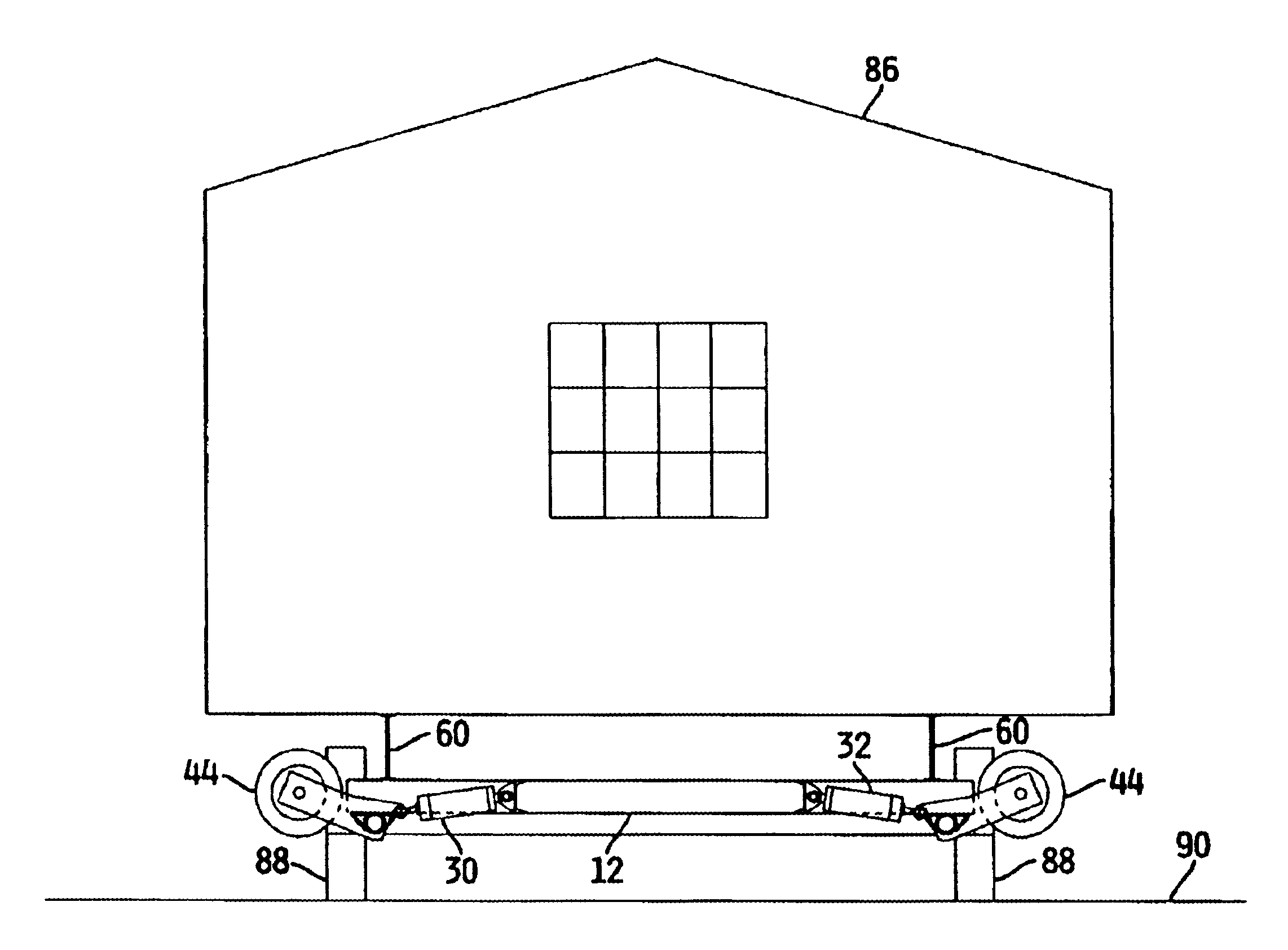
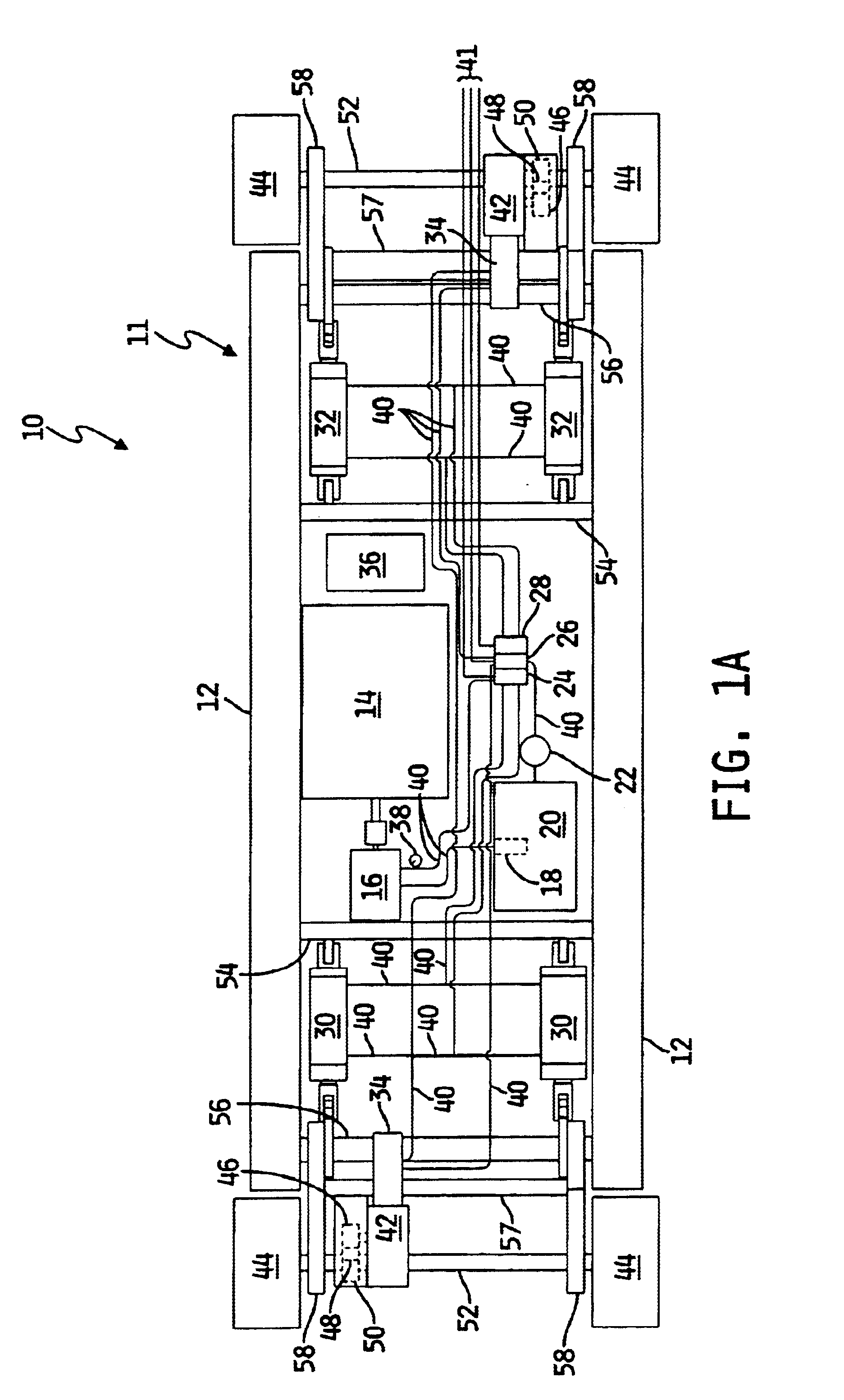
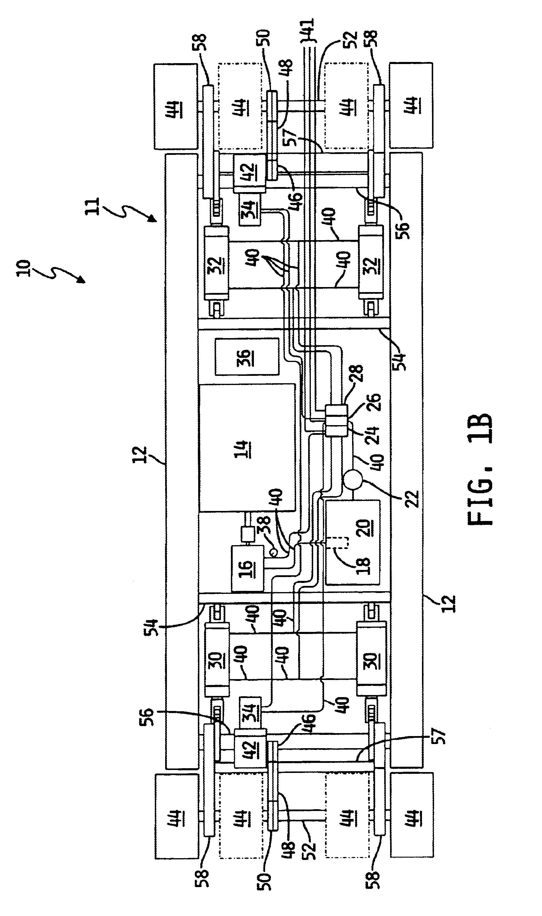
A mobile home transportation apparatus 10 is shown in FIG. 1. The apparatus includes a frame structure 11 containing a plurality of load-bearing frames 12, illustratively two load-bearing I-beams. A drive mechanism 14, for example, a gas engine, electric motor, electric actuator, etc., is coupled to the frame structure 11 by suitable mechanisms, such as bolts, screws, or clamps. Drive mechanism 14 is coupled to and provides power to a hydraulic pump 16 coupled to the frame structure 11. ...


PUM


Abstract

An apparatus for the movement of mobile homes, sectional homes, and manufactured homes is disclosed. The apparatus is self-propelled by a drive mechanism and a hydraulic system. The apparatus facilitates the horizontal and vertical movement of the home during transportation, relocation, and service of the home.

Description

TECHNICAL FIELD OF THE DISCLOSUREThe present disclosure generally relates to a self-propelled apparatus for use in the movement of loads. In particular, the present disclosure relates to an apparatus for use in the movement of mobile and sectional homes.BACKGROUND OF THE DISCLOSUREMobile and sectional homes are generally constructed remotely from the location where the home will be used. Once a home is constructed it is moved to its final location. Additionally, mobile and sectional homes may be moved multiple times during the life of the home. Accordingly, the homes are constructed with a frame structure that rests upon two or more steel I-beams that run the length of the home. The I-beams facilitate the movement of the home from one location to another. Wheels may be permanently attached to the I-beams providing the home with a mode of movement. Conversely, some mobile and sectional homes do not have wheels attached to the I-beams and must be loaded on a trailer that attaches to t...

Claims


Application Information

Patent Timeline
Patent Type & Authority Patents(United States)
IPC IPC(8): B60P1/02E04G23/00E04G23/06B60P3/022
CPCE04G23/06B60P1/027
Inventor JUSTICE, JERRY V.
Owner JUSTICE JERRY V
Why Eureka
Try Eureka