Garment with self-opening vent or pocket

a technology of vents and pockets, applied in protective garments, chemical protection, breathing protection, etc., can solve the problems of cumbersome access to contents, and achieve the effect of facilitating air flow

Inactive Publication Date: 2005-02-01
LINEWEIGHT
View PDF34 Cites 27 Cited by
  • Summary
  • Abstract
  • Description
  • Claims
  • Application Information

AI Technical Summary

Benefits of technology

The closure system of the present invention has a spring member with two arms spaced on opposite sides of the slit opening of a pocket or ventilation opening, formed, for example, in a garment. The spring member is formed of a resilient material such as nylon. In its undeformed condition, the spring member arms are curved above and below the plane of the flexible fabric containing the opening. When the closure, be it zipper, snaps, buttons, hook and loop fasteners, or otherwise, is closed, the spring force of the spring member is overcome, and the pocket or ventilation opening is closed in a conventional fashion. When the closure is opened, the restorative force of the spring member arms causes the flaps on opposing sides of the opening to spread apart. The spring member may be U-shaped or a closed loop, and it may be fastened to the fabric to surround the closure, or may be formed as a part of the closure and attached to the fabric. The wide opening of the mouth facilitates air flow through a ventilation opening, and one-handed unobstructed access to contents of a pocket.

Problems solved by technology

If the side flaps of the opening remain adjacent one another, air passage therethrough may be restricted in the case of a vent, or access to the contents may be cumbersome in the case of a pocket.

Method used


Image

  • Garment with self-opening vent or pocket
  • Garment with self-opening vent or pocket
  • Garment with self-opening vent or pocket

Examples


Embodiment Construction

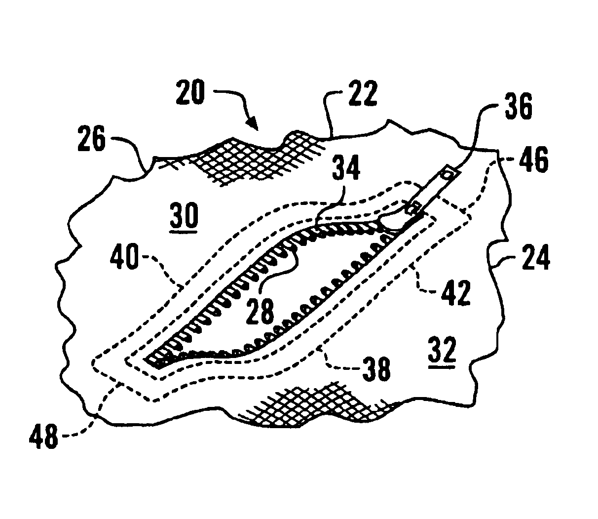
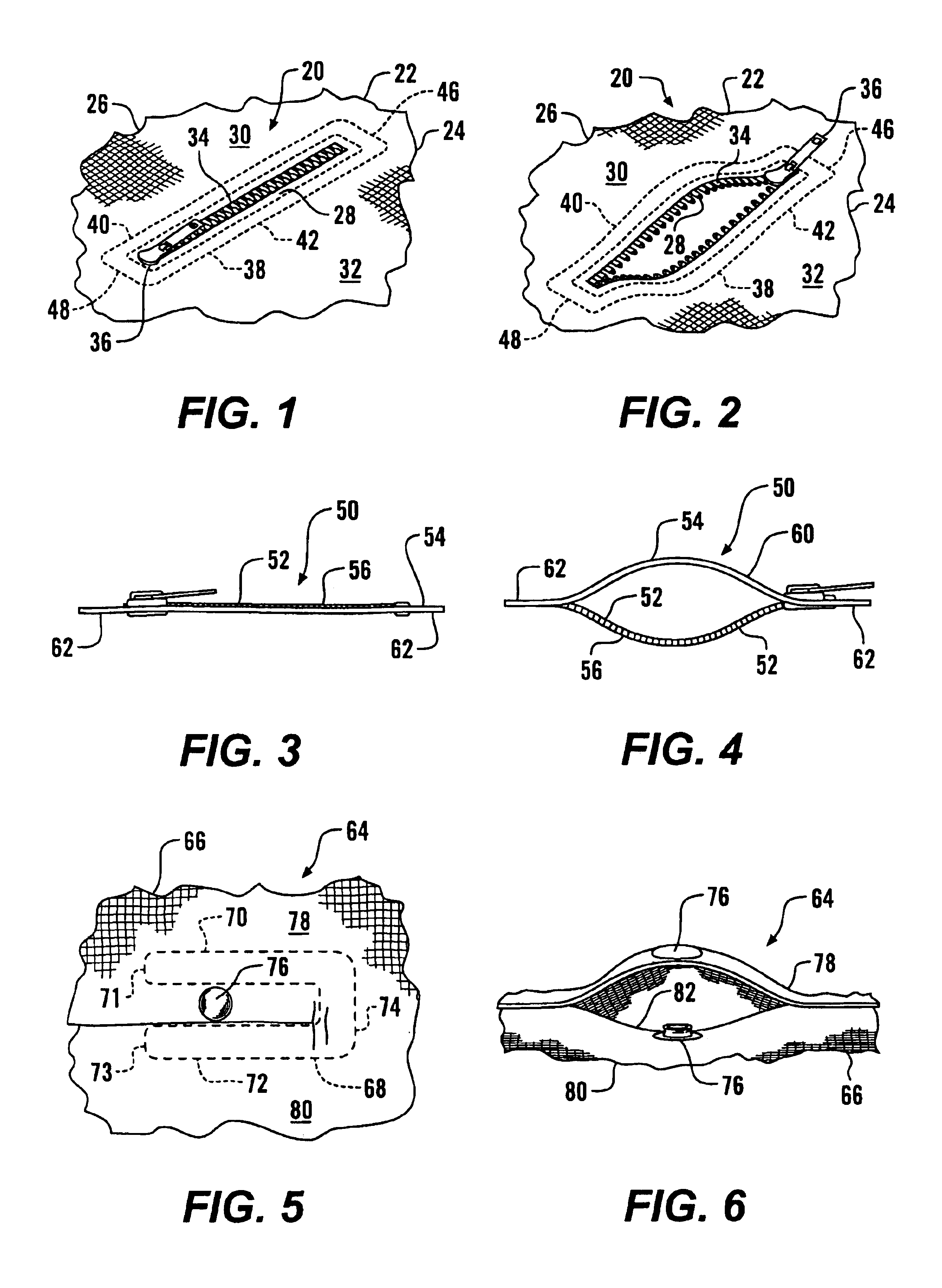
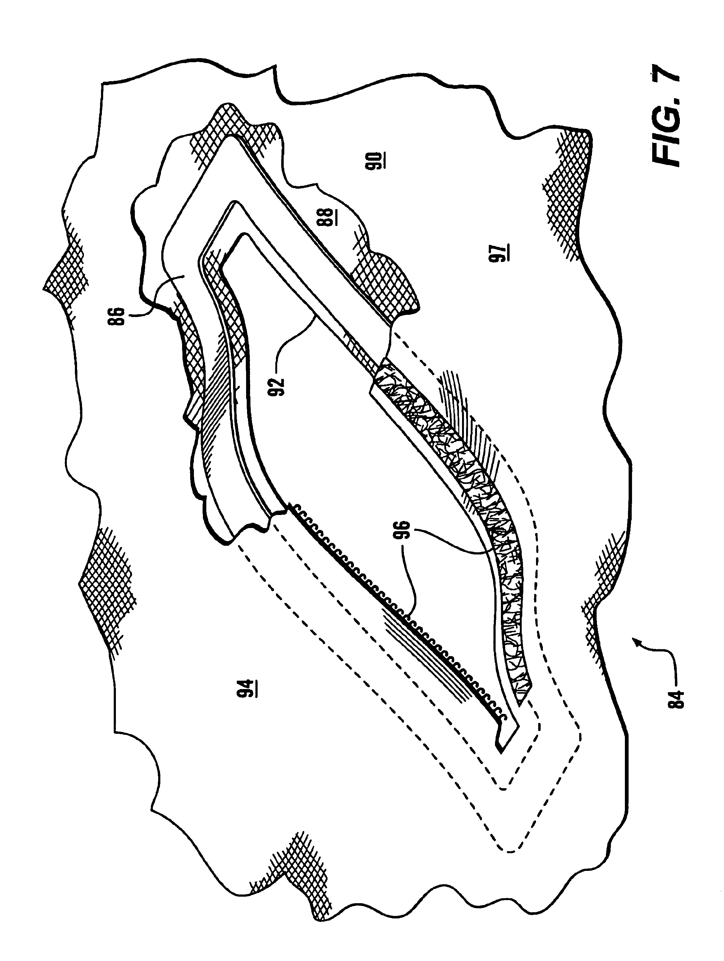
Referring more particularly to FIGS. 1-8, wherein like numbers refer to similar parts, a closure assembly 20 is shown in FIGS. 1 and 2. The closure assembly 20 may be used to resealably cover a pocket or air vent in a garment 22, such as the one shown in FIG. 8, or in a backpack, luggage, accessory, or other device into which ready access is desired. The closure assembly 20 is fixed to the flexible fabric substrate 24 of the item to which it is mounted, for example the shell 26 of the garment 22. As shown in FIG. 2, the fabric substrate 24 has a slit opening 28 which divides a first side flap 30 from a second side flap 32. A closure 34 such as a zipper, one or more snaps, ties, buttons, or hook and loop fasteners, is secured between the first side flap 30 and the second side flap 32. The closure 34 itself operates in a conventional fashion. The illustrated zipper closure is opened by grasping the zipper pull 36 and advancing from one end of the closure to the other.

A spring member 3...


PUM


Abstract

A garment with a flexible fabric shell has a pocket or vent opening with a resealable closure such as a zipper, snaps, or hook and loop fasteners, which is operable between a closed position, in which the opening in the shell is closed, and an open position, in which the opening in the shell is revealed. A resilient spring member of springy plastic, composite, metal or other material is mounted to the fabric around the opening, and has two arms which have portions which are displaced vertically from one another when the closure is open, but which are resiliently compressed into a common plane when the closure is sealed. Each time the closure is opened, the spring member urges portions of the shell on either side of the flap apart, to thereby enlarge the area of the opening and permit access or air flow therethrough.

Description

STATEMENT AS TO RIGHTS TO INVENTIONS MADE UNDER FEDERALLY SPONSORED RESEARCH AND DEVELOPMENTNot applicable.BACKGROUND OF THE INVENTIONAdjustable garments can be a great aid to human effectiveness, particularly in performing complicated or strenuous activities outdoors. Strategically placed pockets can make important supplies and accessories readily available in a convenient location for the wearer of the garment. Moreover, zippered vent openings in thermally important positions can provide ventilation on demand to rapidly reduce the temperatures within the garment during periods of heavy exertion, or, alternatively to maintain temperatures when the wearer is at rest.Pockets and vent openings are closed with conventional fasteners such as zippers, snaps, string ties, and hook and loop fastening systems. However, depending on the location of the opening, the disposition of the wearer's limbs, the stance of the wearer, wind conditions, etc., the openings, once the fasteners have been r...

Claims


Application Information

Patent Timeline
Patent Type & Authority Patents(United States)
IPC IPC(8): A41D27/00A41D27/28A42B3/08A42B3/18A42B3/22A42B3/12A42B3/04A42B3/32A42B3/10F41H1/00F41H1/02F41H1/04A62B17/00
CPCA41D27/28A42B3/08A42B3/10A42B3/12A42B3/326A62B17/006F41H1/04F41H1/02Y10T24/3651Y10S2/01Y10T24/2708Y10T24/253Y10T24/25
Inventor CRYE, CALEB CLARKFEHLBERG, ERIC OWENTHOMPSON, GREGG M.
Owner LINEWEIGHT
Why Eureka
Try Eureka