Combination lock capable of being opened by a key or inhibited the same

a combination lock and key technology, applied in the field of combination locks, can solve the problems of inability to manufacture, difficult to loosen sealing caps, and inability to disclose integral combination locks and padlocks,

Inactive Publication Date: 2005-02-01
LIN CHU PAO FENG
View PDF7 Cites 69 Cited by
  • Summary
  • Abstract
  • Description
  • Claims
  • Application Information

AI Technical Summary

Benefits of technology

It is an object of the present invention to provide a combination lock comprising a substantially parallelepiped body; a U-shaped shackle having a long leg and a short leg; a plurality of parallel dials disposed at one side of the body with a lower portion of the long leg being releasably locked therein; a longitudinal bore disposed at the other side of the body, the longitudinal bore including an upper receiving hole, a lower cavity, an intermediate channel in communication with both the receiving hole and the cavity; and a key opening mechanism disposed in the longitudinal bore, the key opening mechanism comprising a first spring; a cylinder slidably provided in the receiving hole, the cylinder including an upper bore with a terminating end of the short leg being received therein in a locked position; a bottom shoulder with the first spring being put on, a lower bore in communication with the upper bore, a ring disposed between the upper and lower bores, a plurality of longitudinal ridges having an inclined bottom end, the ridges being provided on an inner wall of the lower bore and being equally spaced apart therearound, a first ratchet member formed on a lower portion of the shoulder, and two opposite tabs on an outer surface; a sleeve including two opposite recesses on an inner surface with the tabs received therein when the sleeve is put on the cylinder, the sleeve being urged upwardly by the first spring; a trigger member upwardly biased against a bottom of the ring, the trigger member including a plurality of equally spaced dents on an edge of its upper circular portion, the dents being slidably put on the ridges, and a lower first toothed member; a staged post provided in the lower bore and including a top second toothed member in contact with the first toothed member, and a plurality of equally spaced projections on an upper part of an outer surface so that a longitudinal groove is formed between two

Problems solved by technology

While the patent may be suitable for the particular purpose to which it addresses, it still has the drawbacks of being weak of certain components, possible loosening of sealing cap, an

Method used


Image

  • Combination lock capable of being opened by a key or inhibited the same
  • Combination lock capable of being opened by a key or inhibited the same
  • Combination lock capable of being opened by a key or inhibited the same

Examples


Embodiment Construction

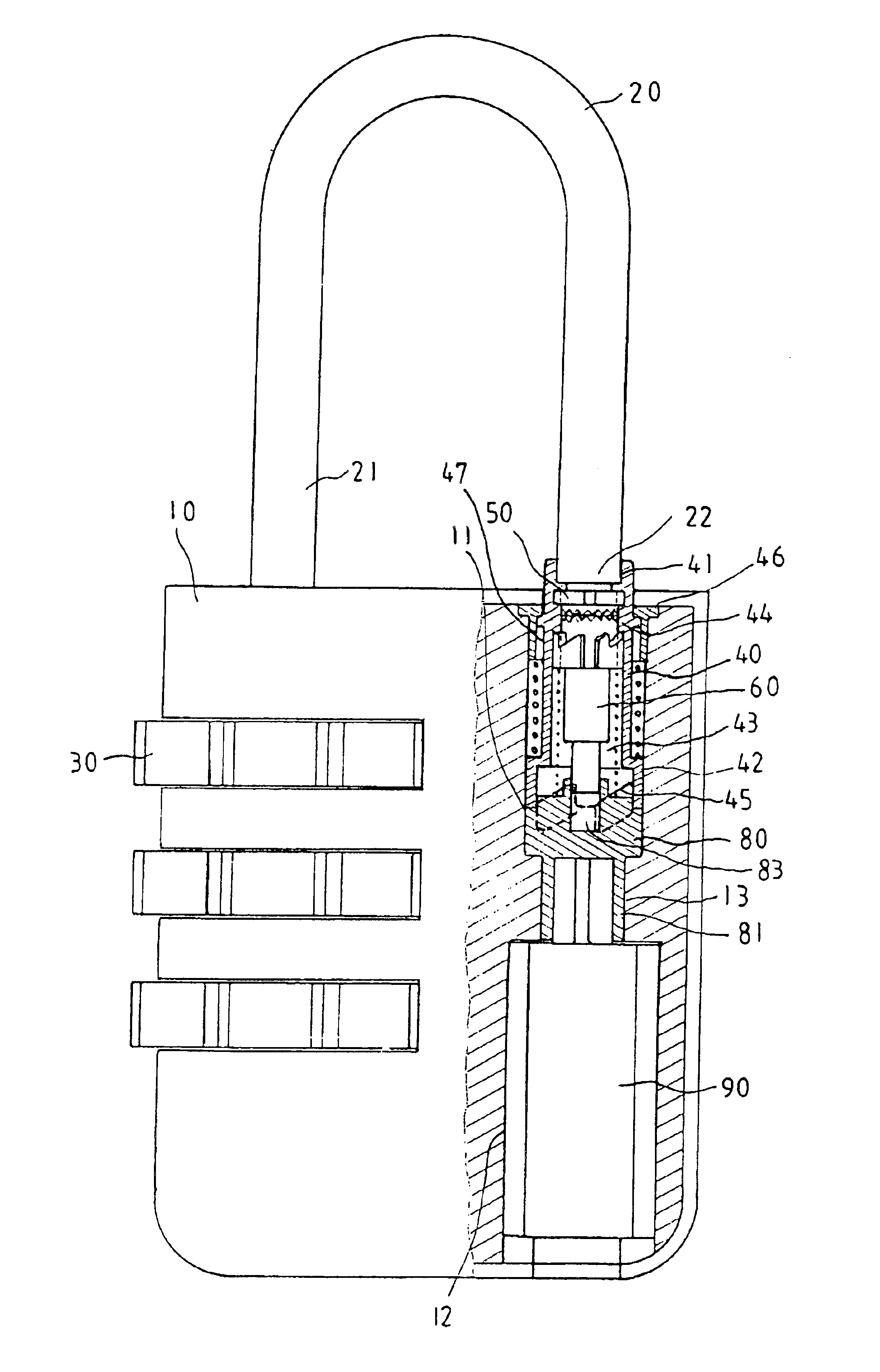
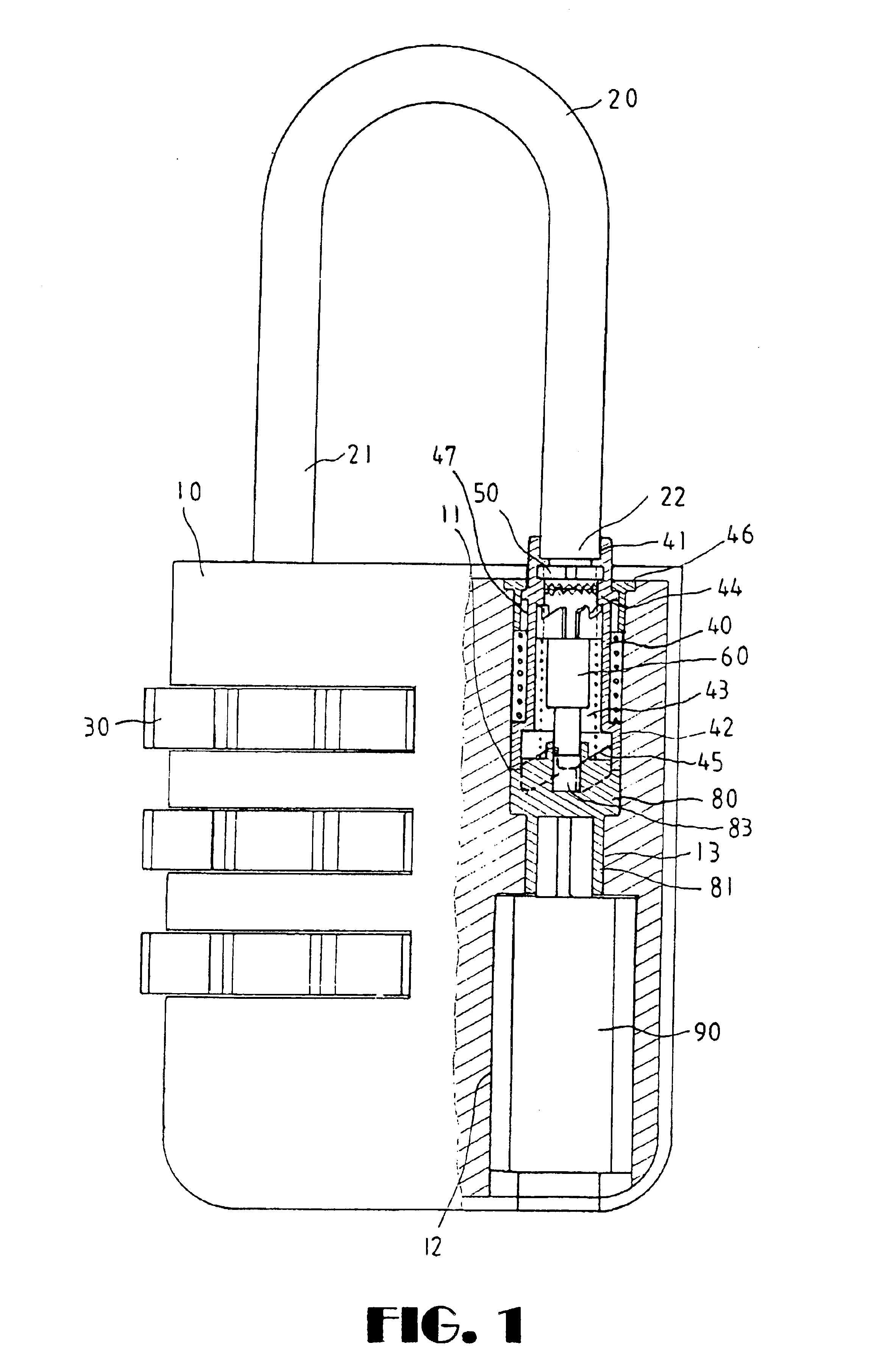
Referring to FIGS. 1 to 12, a combination lock constructed in accordance with the invention is shown. The combination lock comprises a substantially parallelepiped body 10, a U-shaped shackle 20 having a long leg 21 and a short leg 22, a plurality of parallel dials 30 at one side of the body 10 with a lower portion of the long leg 21 being releasably locked therein, and a key opening mechanism provided in a longitudinal bore at the other side of the body 10 (i.e., one shown in the sectional portion of FIG. 1), the longitudinal bore comprising an upper receiving hole 11, a lower cavity 12, an intermediate channel 13 in communication with both the receiving hole 11 and the cavity 12. A terminating end of the short leg 22 is also releasably locked in a top of the key opening mechanism (e.g., the receiving hole 11). The components of the key opening mechanism and its assembly and operations will be described in detail below.

A cylinder 40 is slidably provided in the receiving hole 11. Th...


PUM


Abstract

A combination lock capable of being opened by a key or inhibited the same is disclosed. In the locked position inserting a key into a lock core for turning an abutment member will open the lock. In the unlocked position press the trigger member for moving a post down until grooves clear from ridges, rotate the post a predetermined degree to matingly engage first and second toothed members together, release a trigger member to cause both itself and the post to move up, inclined bottom ends of ridges are gradually engaged with and finally stopped by a second ratchet member, the post is stopped from moving up, and a space between the post and a top hole of the abutment member is reduced sufficiently to inhibit a short leg from moving out of an upper bore by turning the key.

Description

BACKGROUND OF THE INVENTION1. Field of the InventionThe present invention relates to combination locks and more particularly to a combination lock which can be opened by an authorized person by means of a key in addition to the typical opening by arranging dials into a numeral sequence desired by the user. Further, the authorization can be inhibited.2. Description of Related ArtCombination locks are well known. One particular type of combination lock is disclosed in U.S. Pat. No. 5,715,709. While the patent may be suitable for the particular purpose to which it addresses, it still has the drawbacks of being weak of certain components, possible loosening of sealing cap, and difficult of manufacturing due to excessive internal components. Moreover, it is known that a padlock can only be opened by a key. Unfortunately, an integral combination lock and padlock has not been disclosed as far as the present inventor is aware. Also, it is understood that a user may forget the combination of...

Claims


Application Information

Patent Timeline
IPC IPC(8): E05B37/02E05B37/00E05B67/00E05B67/24
CPCE05B67/24E05B37/025E05B37/0034Y10T70/415Y10T70/424Y10T70/459Y10T70/7141Y10T70/7147
Inventor LIN, CHU PAO-FENG
Owner LIN CHU PAO FENG
Why Eureka
Try Eureka