Supercharge Your Innovation With Domain-Expert AI Agents!

Modular drilling rig substructure

a technology of drilling rigs and substructures, applied in drilling casings, drilling pipes, power driven tools, etc., can solve the problem that the modular substructure of the drilling rigs of the jr. is not provided by the drilling rigs

Inactive Publication Date: 2005-02-01
HELMERICH & PAYNE INC
View PDF8 Cites 57 Cited by
  • Summary
  • Abstract
  • Description
  • Claims
  • Application Information

AI Technical Summary

Benefits of technology

The driller side substructure section includes a base having a lower skid suitable to be lowered on, loaded off and transported from a trailer or other vehicle. Parallel to and above the base is a floor frame assembly. Pivotally connected between the base and floor frame assembly are a pair of front legs, a pair of middle legs and a pair of rear legs. The front legs, middle legs and rear legs are each pivotally connected to the base. Likewise, the front legs, the middle legs and the rear legs are pivotally connected to the floor frame assembly of the driller side substructure section. Accordingly, the floor frame assembly, the base, the front legs, and the rear legs form a parallelogram. The floor frame assembly can thus move between an upright, in-use position and a lower position parallel to and adjacent to the base for transportation.
The off driller side substructure section operates in the same manner. The off driller side substructure section includes a base, a pair of front legs, middle legs and a pair of rear legs. The front legs, middle legs, and rear legs are each pivotally connected to the base. Likewise, the front legs, middle legs, and rear legs are each pivotally connected to a floor frame assembly of the off driller side substructure section. Accordingly, the floor frame assembly, the base, the front legs and the rear legs together form a parallelogram. In order to assemble a drilling or workover rig substructure, the driller side substructure section and the off driller side substructure section are each transported to a selected rig site in a lowered position. The base of the driller side substructure section is adjacent a dra...

Problems solved by technology

While the floor panels are adequate for the purpose of support, they typically do not form a liquid-tight floor section.
Bierscheid, Jr. does not, however, provide a modular substructure.

Method used


Image

  • Modular drilling rig substructure
  • Modular drilling rig substructure
  • Modular drilling rig substructure

Examples


Embodiment Construction

The embodiments discussed herein are merely illustrative of specific manners in which to make and use the invention and are not to be interpreted as limiting the scope of the instant invention.

While the invention has been described with a certain degree of particularity, it is to be noted that many modifications may be made in the details of the invention's construction and the arrangement of its components without departing from the spirit and scope of this disclosure. It is understood that the invention is not limited to the embodiments set forth herein for purposes of exemplification.

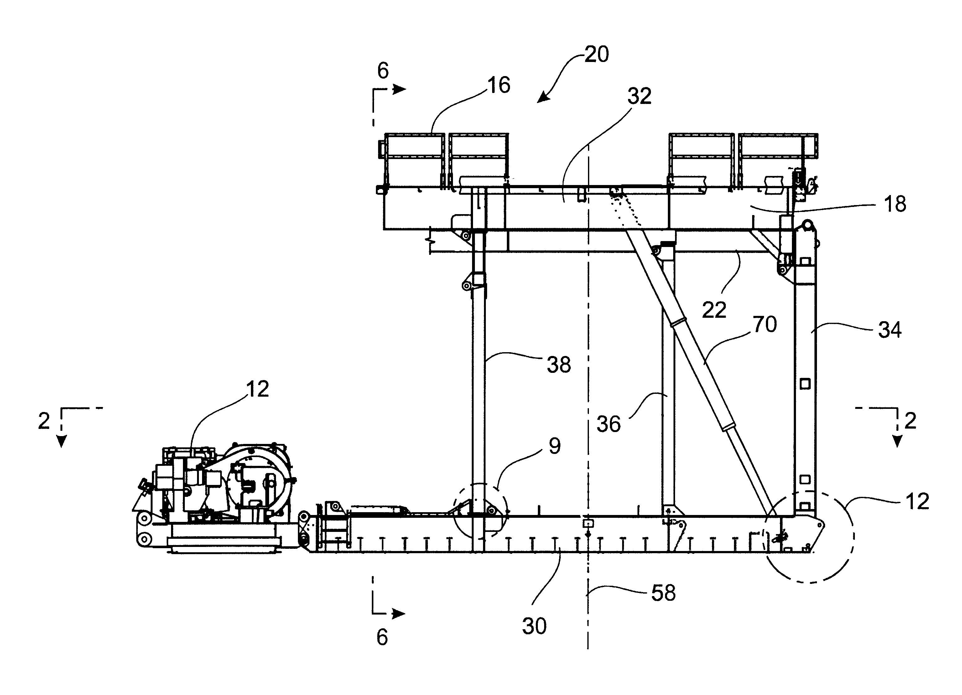
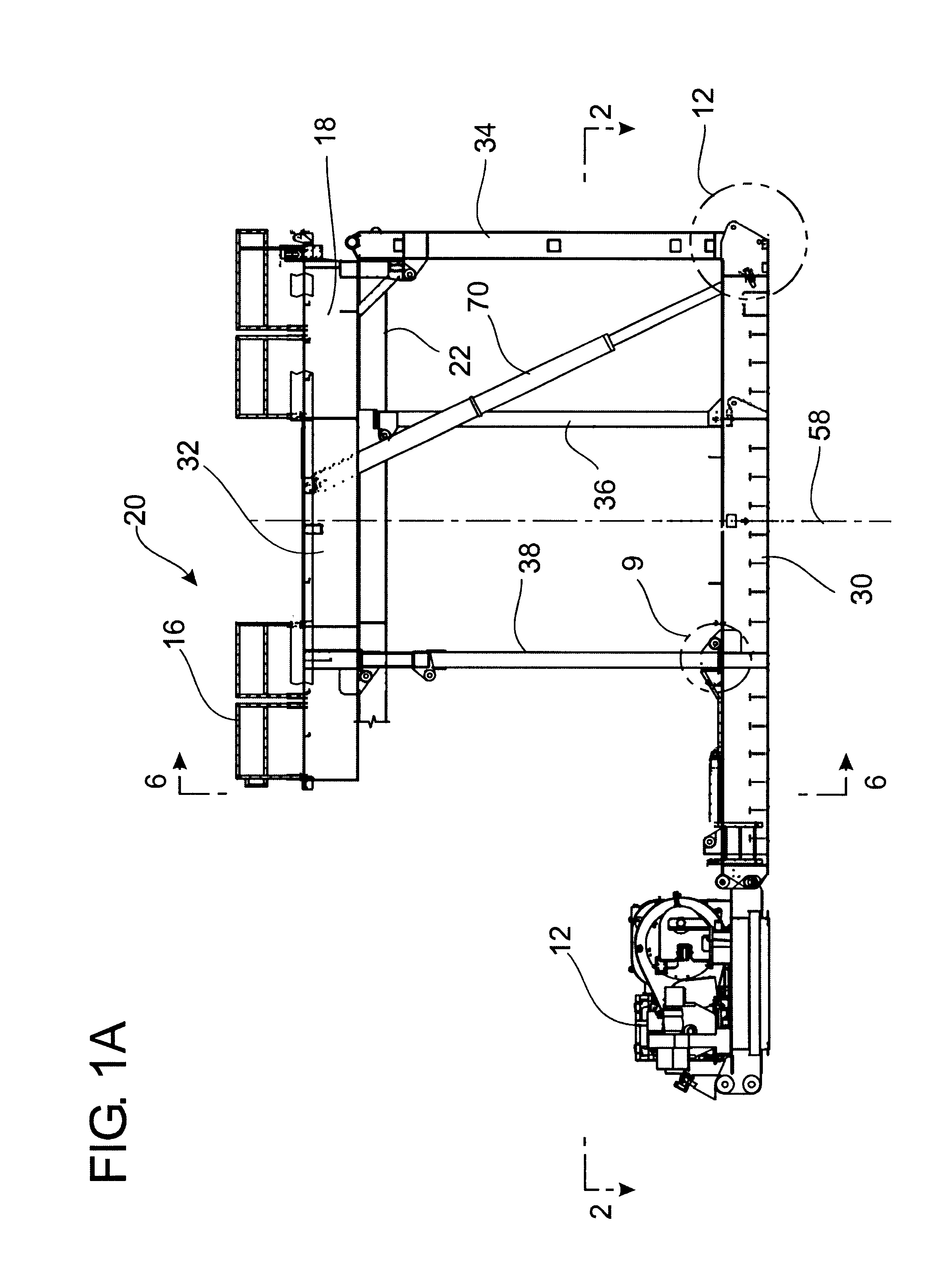
Referring to the drawings in detail, FIG. 1A is a side elevational view of a modular drilling rig substructure 10 constructed in accordance with the present invention. As seen in FIG. 1, the rig substructure is an upright, in use and fully assembled condition and in place adjacent to a drawworks 12. A mast (not shown) would be brought to and installed on the rig substructure 10.

The rig substructure 1...


PUM


Abstract

A process to transport and assemble a drilling or workover rig substructure. The process includes the steps of transporting a driller side substructure section and an off driller side substructure section to a rig site so that the sections are spaced from and parallel to each other. A center substructure section is transported to the rig site. The center substructure section is moved into a space between the driller side and the off driller side sections. The center substructure section is thereafter connected to the driller side and to the off driller side subsections. A floor of the driller side substructure and a floor of the off driller side substructure are raised while both connected to the center substructure section from a transport position to a use position while maintaining the floors parallel to the bases.

Description

BACKGROUND OF THE INVENTION1. Field of the InventionThe present invention relates to a modular drilling or workover rig substructure which may be transported to and from a rig site without entirely dismantling the substructure. In particular, the present invention is directed to a modular drilling rig substructure that may be transported to and from a rig site with various drill floor equipment and hand rails remaining in place and that minimizes liquid discharge by providing an integrated containment and drainage system.2. Prior ArtA drilling rig substructure is one important component of a drilling or workover rig. Typically, a drilling rig substructure includes a raised platform or drilling floor which is above the level of a main deck or cellar deck and above the level of a well head, a blowout preventer and other equipment. An upstanding mast is connected to a floor of the rig and is often supported by the substructure. The mast may extend from 30 to 60 meters so that a substan...

Claims


Application Information

Patent Timeline
IPC IPC(8): E21B7/02E21B15/00
CPCE21B15/00
Inventor ORR, ALANTREVITHICK, MARK
Owner HELMERICH & PAYNE INC
Features
  • R&D
  • Intellectual Property
  • Life Sciences
  • Materials
  • Tech Scout
  • Unparalleled Data Quality
  • Higher Quality Content
  • 60% Fewer Hallucinations
Learn More