
Suppressor for a paintball marker

a paintball marker and suppressor technology, applied in the field of suppressors or suppressors, can solve the problems of patents that cannot adapt, no commercial paintball suppressors are currently on the market, and none of the current silencers are self-aligning, so as to achieve the effect of not giving away your position in a gam

Inactive Publication Date: 2005-02-01
SHAFER GORDON SCOTT
View PDF25 Cites 23 Cited by
  • Summary
  • Abstract
  • Description
  • Claims
  • Application Information

AI Technical Summary

Benefits of technology

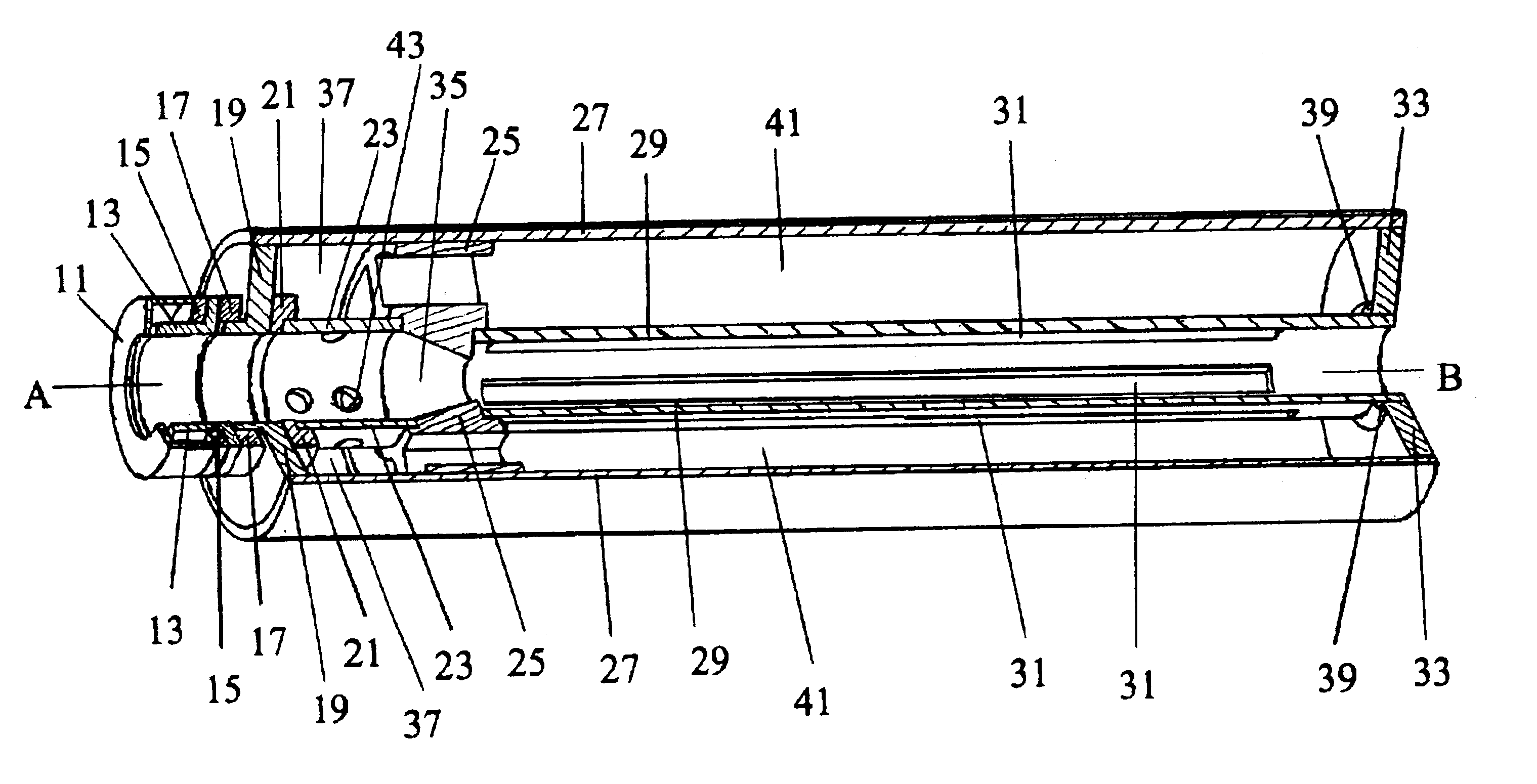
"The invention is a Suppressor for Paintball Markers that reduces the loud sound and flash when a marker is fired. The Suppressor is designed to fit different types of Paintball Markers and is easy to clean. It is also designed to be easily disassembled for cleaning without scratching or damaging the marker. The invention includes an internal structure with a proximal and distal inner tube that self centers and aligns with the marker's barrel, and an internal disk that self-adapts to different barrel diameters. The invention also includes an acoustical element to fill the space created by the two internal chambers. The technical effects of the invention include reducing the noise and flash of Paintball Markers, improving the accuracy of the marker's trajectory, and providing a more comfortable and safe experience for players."

Problems solved by technology

There are no commercial Paintball Suppressors currently on the market, mostly due to the in-depth regulations, money and requirements that the BATF, (Bureau of Alcohol Tobacco and Firearms), requires to own, build or manufacture silencers.
Unfortunately due to the short distances involved to shoot at each other with paintballs, which is usually anywhere from 30 feet to 150 feet.
None of the current Suppressor, (also called Silencer), patents have the ability to adapt to a variable range of barrel diameters.
Further, none of the current Silencers are self aligning and centering along the firing axis of a projectile device across a variable range of barrel diameters.

Method used


Image

  • Suppressor for a paintball marker
  • Suppressor for a paintball marker

Examples


Embodiment Construction

Detailed descriptions of the preferred embodiment are provided herein. It is to be understood, however, that the present invention may be embodied in various forms. Therefore, specific details disclosed herein are not to be interpreted as limiting, but rather as a basis for the claims and as a representative basis for teaching one skilled in the art to employ the present invention in virtually any appropriately detailed system, structure or manner.

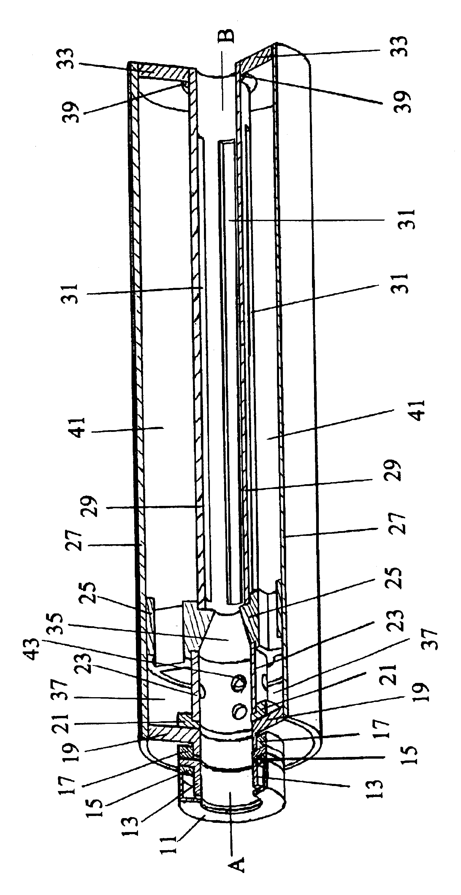
Turning now to the drawings, in which like reference characters indicate corresponding elements throughout the drawing. With reference to the drawing, of a singular, 3D, perspective drawing with longitudinal cut away. The apparatus, here after to be called a Suppressor, for suppressing muzzle pop and / or crack from a paintball marker. The Paintball Marker, (also known as a Paintball Gan), or other compressed gas gun, which from here after will be known as a Marker. According to the FIGURE, the Suppressor is comprised of three main elements,...


PUM


Abstract

An apparatus for suppressing muzzle pop and / or crack in a Paintball Marker, (also known as a Paintball gun), or other compressed gas gun with an outer shell which connects to a proximal end cap with centered opening to be secured to a muzzle of a Paintball marker by an attachment piece, and a distal end cap with an centered exit opening. An internal structure that is centered along the longitudinal firing axis of the apparatus, between the proximal end cap and distal end cap, and being the bore for the proximal end opening for accepting the paintball marker barrel, and the distal exit opening in the center of the distal end cap for the exiting Paintball. The attachment piece and internal structure will accept a wide range of production paintball barrel diameters, as well as be self centering and aligning along the longitudinal firing axis of the apparatus.

Description

CROSS REFERENCE TO RELATED APPLICATIONSNot ApplicableSTATEMENT REGARDING FEDERALLY SPONSORED RESEARCH OR DEVELOPMENTNot ApplicableDESCRIPTION OF ATTACHED APPENDIXNot ApplicableBACKGROUND OF THE INVENTIONThis invention relates generally to the field of Silencers or Suppressors and more specifically to A Suppressor for a Paintball Marker. More specifically this invention relates to a suppressor that adapts to a range of Paintball barrel diameters and at the same time self aligns and self centers itself along the axis of the bore of the Paintball Marker barrel and the bore of the Suppressor.The terms used below, such as proximal and distal, relate to the firing direction as well as the end closest and furthermost from the firer with arm out stretched shooting at a target away form his body. Proximal refers to the end of the Suppressor that attaches to the end of the barrel and distal refers to the end of the suppressor furthermost away, the part where the paintball exits after being fi...

Claims


Application Information

Patent Timeline
Patent Type & Authority Patents(United States)
IPC IPC(8): F41B11/00F41A21/30
CPCF41B11/00F41A21/30
Inventor SHAFER, GORDON SCOTT
Owner SHAFER GORDON SCOTT
Learn More