Vehicular lamp employing led light sources

a technology of led light sources and lamps, applied in the field of lamps, can solve the problems of dim lamps, inability to individually control the reflection of light from led light sources,

Inactive Publication Date: 2005-02-01
KOITO MFG CO LTD
View PDF9 Cites 38 Cited by
  • Summary
  • Abstract
  • Description
  • Claims
  • Application Information

AI Technical Summary

Benefits of technology

In view of the foregoing problem, it is an object of the present invention to provide a vehicular lamp employing a plurality of LED light sources and utilizing an indirect illumination technique wherein the total light emitted in the direction toward the front face of the lamp is increased by more effectively using the light from the LED light sources.

Problems solved by technology

However, in such a conventional vehicular lamp, since a common reflector is shared by a plurality of LED light sources arranged in a line, the reflection of light from each LED light source cannot be individually controlled.
As a result, there is a problem that the lamp is rather dim when observed from the front.

Method used


Image

  • Vehicular lamp employing led light sources
  • Vehicular lamp employing led light sources
  • Vehicular lamp employing led light sources

Examples


Embodiment Construction

A first preferred embodiment of a vehicular lamp constructed according to the present invention will be explained with reference to the accompanying drawings.

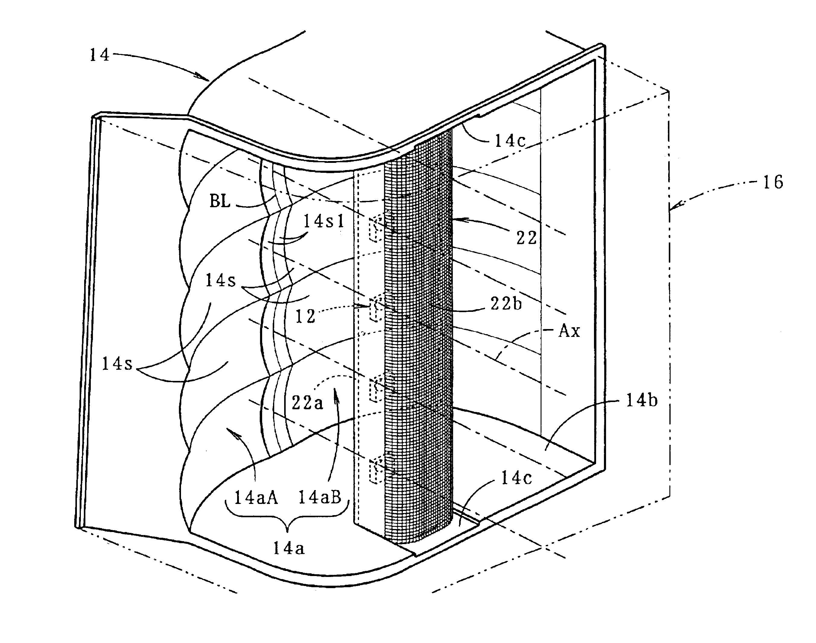
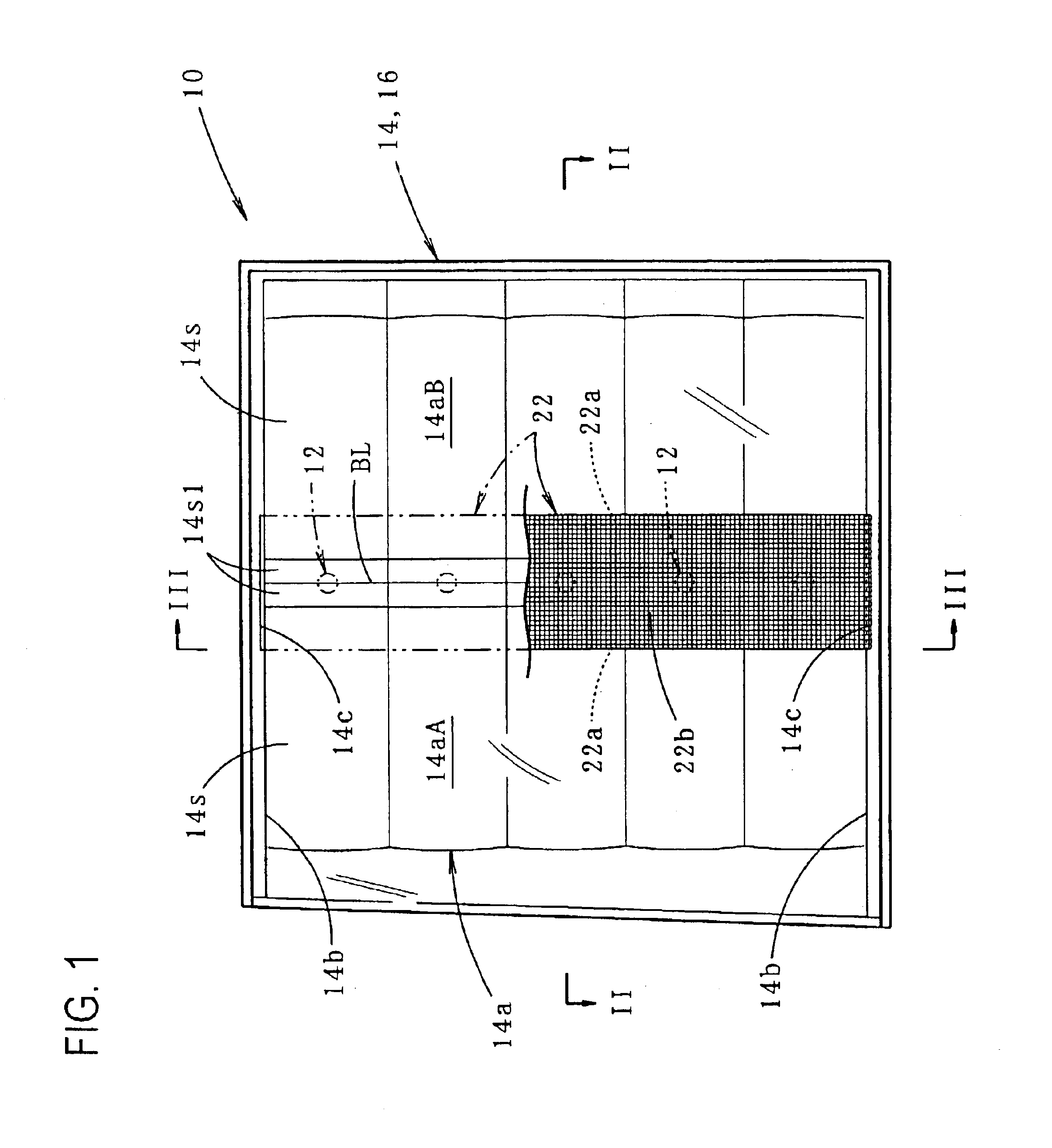
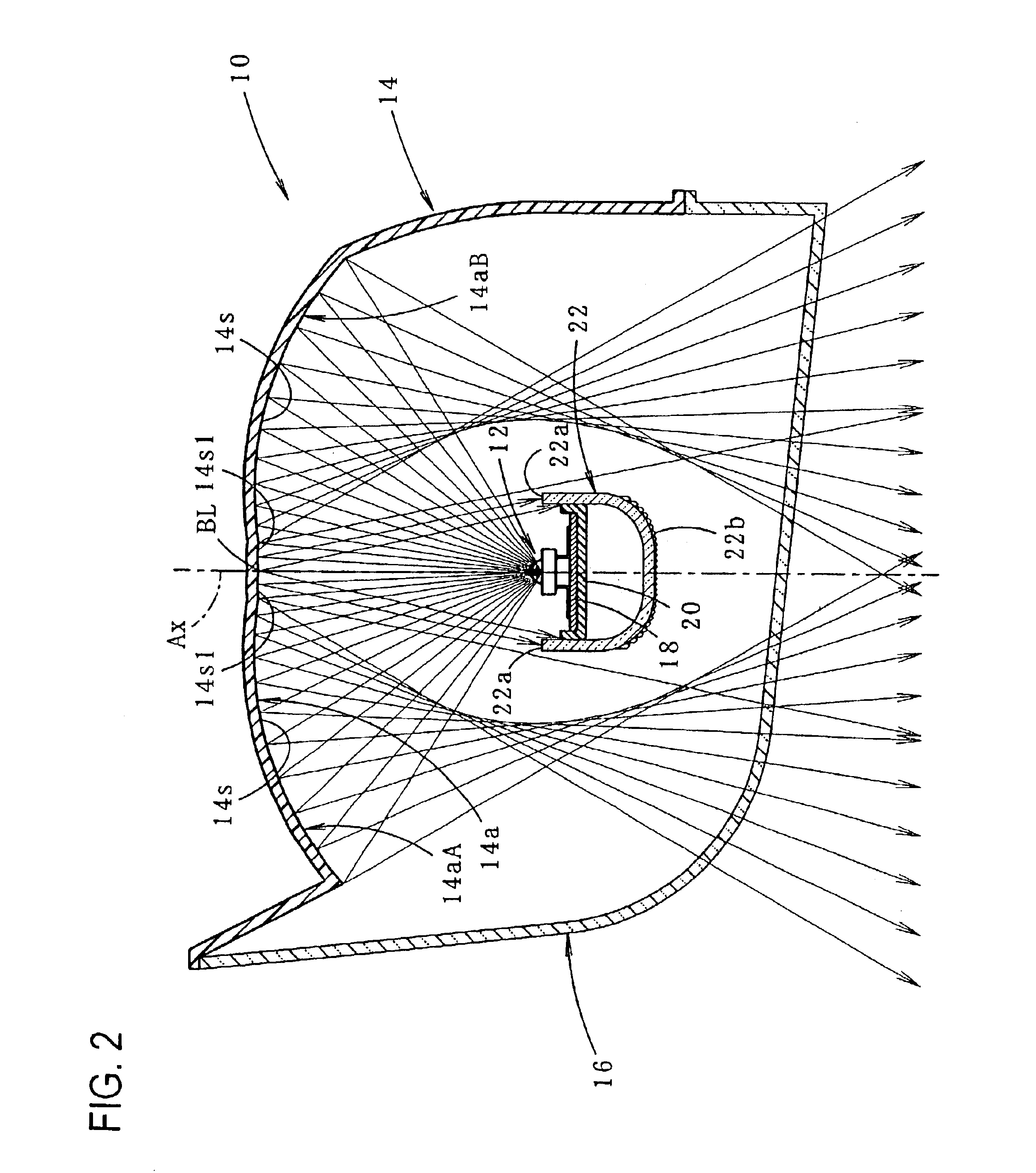
FIG. 1 is a front view of a vehicular lamp constructed according to the first preferred embodiment, and FIGS. 2 and 3 are sectional views of FIG. 1 taken along line II—II and line III—III, respectively.

As shown in these drawings, the vehicular lamp 10 according to the first embodiment is constituted as a tail lamp designed to be mounted at the left rear end portion of an automotive vehicle. A tail lamp mounted at the right rear end portion of the vehicle is structured symmetrically respect to the tail lamp described herein.

This vehicular lamp 10 includes a plurality of LED light sources 12, a reflector 14 for reflecting light from the LED light sources 12 toward the front of the lamp (that is, in the rearward direction of the vehicle), and a red translucent cover 16 mounted on the front side of the reflector 14. The reflector 1...


PUM


Abstract

A vehicular lamp employing a plurality of LED light sources and arranged to emit light using indirect illumination wherein the total light emittance in the front direction of the lamp is increased by more effectively using the light from the LED light sources. The LED light sources are arranged in a line in the vertical direction such that their direction of light emission is toward the rear of the lamp. The reflecting surface of the reflector is divided into right and left reflecting areas by a boundary line. With this arrangement, a large portion of the light from each LED light source contributes to the light reflected by the reflector. The reflecting areas are divided into a plurality of small reflecting surfaces, preferably two for each LED light source. Thus, it is possible to separately control the reflection of the light from each LED light source by the small reflecting surfaces on both sides of the LED light sources. When the lamp is observed from the front, the number of illuminated areas is greater than the number of LED light sources.

Description

CROSS-REFERENCE TO RELATED APPLICATIONSNot applicableSTATEMENT REGARDING FEDERALLY SPONSORED RESEARCH OR DEVELOPMENTNot applicableREFERENCE TO SEQUENCE LISTING, A TABLE, OR A COMPUTER PROGRAM LISTING COMPACT DISK APPENDIXNot applicableBACKGROUND OF THE INVENTIONThe present invention relates to a vehicular lamp employing a plurality of LED light sources, and more particularly to a vehicular lamp of a type which is configured so as to emit light using an indirect illumination technique.Many vehicular lamps including a LED light source have been employed in recent years. For example, as disclosed in Japanese Patent No. 3,173,453 or Japanese Patent Laid-Open Publication No. 11-306810, a plurality of LED light sources are arranged in a line and mounted in such a manner so as not to be visible from the front of the lamp. The light output from the LED light sources is directed rearward toward the reflector, and the light from the LED light sources is reflected toward the front of the lamp ...

Claims


Application Information

Patent Timeline
Patent Type & Authority Patents(United States)
IPC IPC(8): F21S8/10F21V13/00F21V13/04F21V5/00F21W101/14F21Y101/02
CPCF21S48/215F21S48/218F21S48/24F21S48/2212F21Y2101/02F21V7/0008F21Y2103/003F21Y2103/10F21Y2115/10F21S43/14F21S43/15F21S43/26F21S43/40
Inventor NATSUME, KAZUNORI
Owner KOITO MFG CO LTD
Why Eureka
Try Eureka