All gear infinitely variable transmission

a transmission system and all gear technology, applied in the direction of toothed gearings, belts/chains/gearings, portability lifting, etc., can solve the problems of inefficient torque transfer between the input and output shafts, the efficiency of the engine cannot be maximized for any particular operating condition, and the limitation of the torque which can be carried by the gear system, etc., to achieve uniform velocity ratio

Inactive Publication Date: 2005-02-01
KER TRAIN HLDG
View PDF32 Cites 21 Cited by
  • Summary
  • Abstract
  • Description
  • Claims
  • Application Information

AI Technical Summary

Benefits of technology

The infinitely-variable transmission, according to the present invention, comprises a rotational input member, a rotational output member, a pair of variable velocity-ratio gear sets, a multi-directional coupling associated with the gear sets, and an actuator associated with the coupling. The coupling couples the gear sets to the rotational members over a common angular period so as to provide a uniform velocity ratio between the rotational members over the angular period. The transmission also includes a phase angle variator associated with at least one of the gear sets for varying a rotational angular displacement between the gear sets. Consequently, the velocity ratio of the transmission can be varied while maintaining the velocity ratio uniform over the angular period.

Problems solved by technology

However, the conventional transmission results in an inefficient transfer of torque between the input and output shafts since the prime mover must be uncoupled from the transmission output shaft while the planetary gears are switched.
Further, since engine speed must vary in each gear ratio to affect speed change of the output shaft, the efficiency of the engine cannot be maximized for any particular operating condition.
However, as the clutches must be activated each revolution of the driven shaft R, the clutches must be relatively small to be used for high speed applications, thereby limiting the torque which can be carried by the gear system.
However, overrunning clutches can only transfer energy in a single direction, thereby precluding engine drag.
Further, as the variable output transmissions only amplified the positive or negative periods of the square-wave velocity ratio profile, the efficiency and maximum kinematic range of the transmissions was limited.
Further, as discussed above, the overrunning clutches preclude engine drag and reduce the efficiency and maximum kinematic range of the device.
Although the transmission taught by Pires addresses the problems imposed by overrunning clutches on efficiency and kinematic range, the transmission is quite complex.
Further, it is believed that the oscillating crank arms will produce undesirable fluctuations in the velocity ratio of the transmission.
These variations in contact ratio cause excessive gear noise.
Consequently, the load which can be carried by the gears is limited.

Method used


Image

  • All gear infinitely variable transmission
  • All gear infinitely variable transmission
  • All gear infinitely variable transmission

Examples


first embodiment

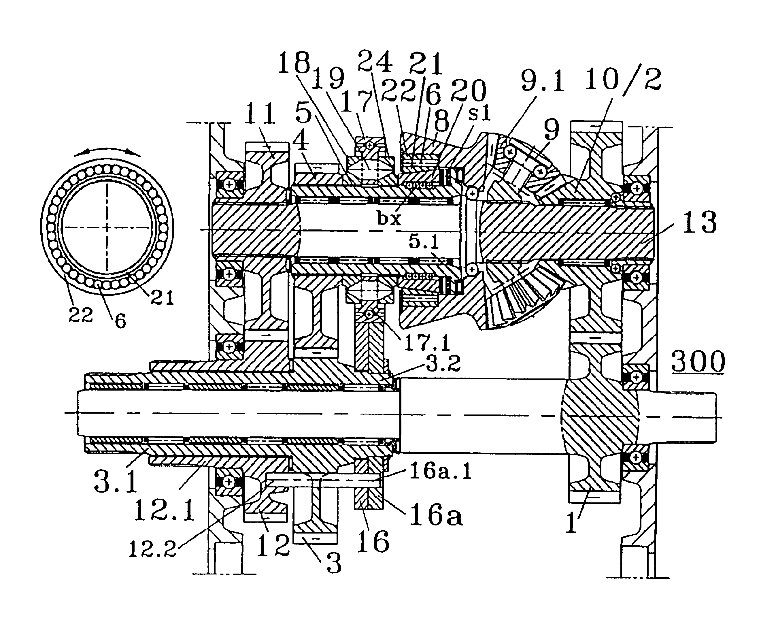
Turning now to FIGS. 2, 2a, one variable-ratio gear assembly of an infinitely-variable transmission 100, according to the present convention, is shown. As above, the transmission 100 includes four identical variable-ratio gear assemblies which are disposed preferably at equal angular intervals around the input shaft 3.1 and the output shaft 1.1, although they may be disposed at unequal angular intervals with a possible reduction in performance. For convenience, only one variable-ratio gear assembly is shown.

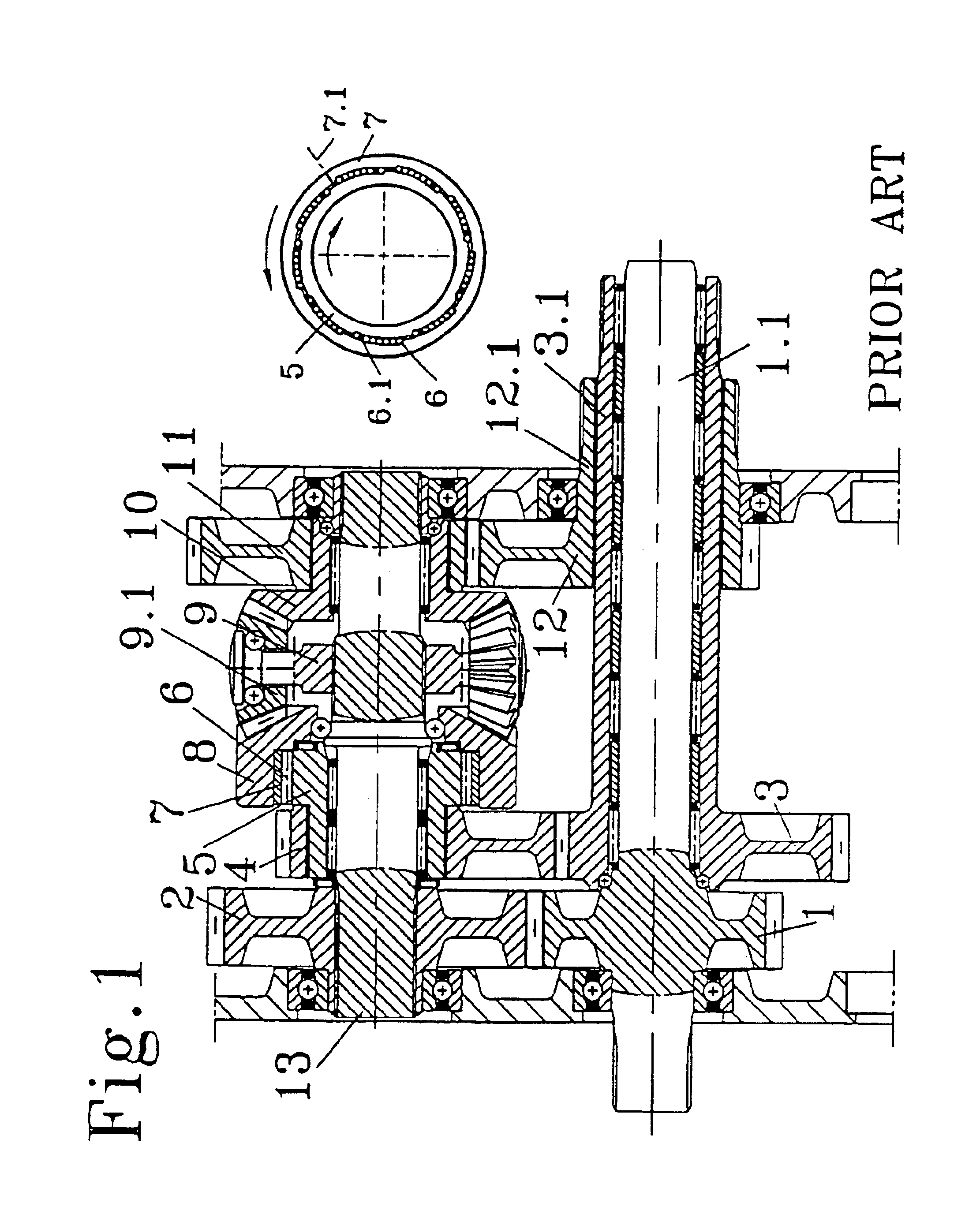
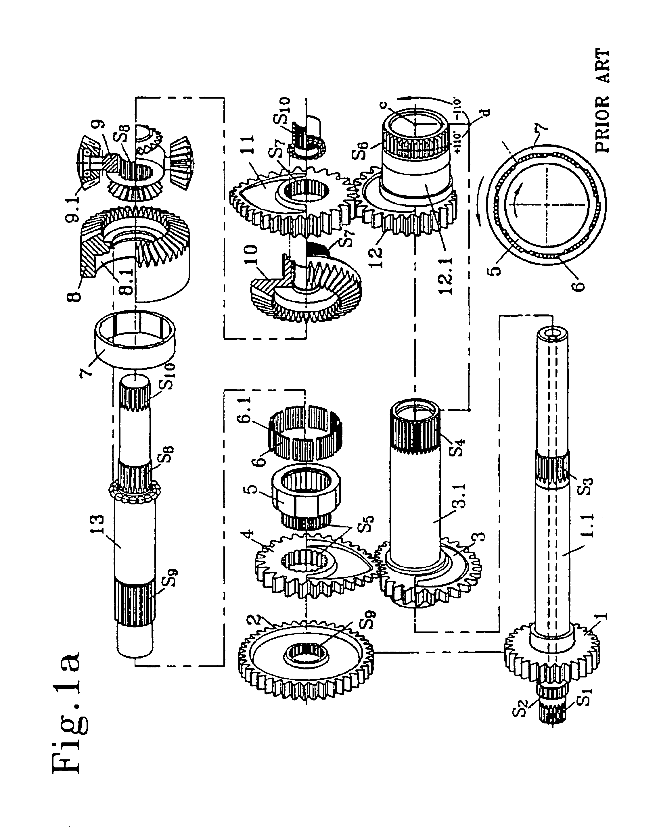
The infinitely-variable transmission 100 comprises a “bevel-bevel”-type transmission, similar in structure to the infinitely-variable “bevel-bevel” transmission shown in FIGS. 1, 1a. However, unlike the “bevel-bevel” transmission shown in FIGS. 1, 1a, the cage 5 of the one-way overrunning clutch is replaced with a sleeve 5.1 provided around the intermediate shaft 13 and splined to the first non-circular driven gear 4. Also, each variable-ratio gear assembly of the transmission 10...

second embodiment

FIG. 2c shows an infinitely-variable “bevel-carrier” transmission 200, according to the present convention. The infinitely-variable transmission 200 is substantially identical to the “bevel-carrier” transmission shown in FIG. 1c, except that the cage 5 of the one-way overrunning clutch is replaced with a sleeve 5.1 provided around the intermediate shaft 13 and splined to the first non-circular driven gear 4, and the one-way overrunning clutch is replaced with a programmable multi-directional coupling and an cam-follower actuator. As shown in FIG. 2d, the amplification of the transmission shown in FIG. 2c has a changed to 300% in both directions, which again represents a dramatic improvement over the prior art.

FIG. 2e summarizes the non-circular gear pairs for the “bevel-bevel” transmission 100, and the “bevel-carrier” transmission 200. Diagrams a) and b) of FIG. 2e depict the first and second non-circular gear pairs for the “bevel-bevel” transmission 100. The first non-circular gear...

third embodiment

Numerous variations of the foregoing embodiments may be realized. FIG. 2f shows an infinitely-variable “bevel-carrier” transmission 300, according to the invention. The “bevel-carrier” transmission 300 is substantially identical to the “bevel-carrier” transmission shown in FIG. 1e, except that the cage 5 of the one-way overrunning clutch is replaced with a sleeve 5.1 provided around the intermediate shaft 13 and splined to the first non-circular driven gear 4, and the one-way overrunning clutch is replaced with a programmable multi-directional coupling and an cam-follower actuator. Due to the 2:1 gear ratio of the differential, the first and second non-circular gear pairs can produce the same angular acceleration. The amplification characteristics of the transmission 300 are similar to those the transmission shown in FIG. 1e in so far as the transmission 300 is capable of producing infinite translation. As will be discussed below, this feature is advantageous when the transmission 3...


PUM


Abstract

An infinitely-variable transmission comprises a rotational input member, a rotational output member, first and second non-circular driving gears coupled to one of the rotational members, and a plurality of variable velocity-ratio gear assemblies disposed about the one rotational member. Each gear assembly comprises an intermediate shaft including first and second non-circular driven gears respectively meshing with the first and second non-circular driving gears. Each gear assembly also comprises a multi-directional coupling associated with the pair of first driven / driving gears and the pair of second driven / driving gears, and an actuator for coupling the first and second variable-ratio gear pairs to the rotational members. The transmission also includes a phase angle variator associated with the variable-ratio gear pairs for varying the rotational angular displacement between the first gear pairs and the second gear pairs of each gear assembly so as to vary the velocity ratio of the transmission as needed.

Description

FIELD OF THE INVENTIONThe present invention relates to gear systems having variable velocity ratios. In particular, the present invention relates to all-gear transmissions whose velocity ratios may be varied continuously over the velocity ratio continuum.BACKGROUND OF THE INVENTIONThe conventional transmission incorporates a number of planetary gears which are selectively coupled between the input and output shafts for changing the velocity ratio of the transmission. However, the conventional transmission results in an inefficient transfer of torque between the input and output shafts since the prime mover must be uncoupled from the transmission output shaft while the planetary gears are switched. Further, since engine speed must vary in each gear ratio to affect speed change of the output shaft, the efficiency of the engine cannot be maximized for any particular operating condition. Therefore, many attempts have been made to provide a transmission whose velocity ratios are infinite...

Claims


Application Information

Patent Timeline
Patent Type & Authority Patents(United States)
IPC IPC(8): F16H29/00
CPCF16H29/00Y10T74/19884Y10T74/19242F16H2035/003
Inventor KERR, JOHN HUGH
Owner KER TRAIN HLDG
Why Eureka
Try Eureka