Parallax panoramagram having improved depth and sharpness

a panoramagram and depth technology, applied in the field of parallax panoramagrams, can solve the problems of inability to consider the display to be a fully perfected visual medium, the depth content of the panoramagram must be restricted,

Inactive Publication Date: 2005-02-01
LEDOR LLC +1
View PDF10 Cites 76 Cited by
  • Summary
  • Abstract
  • Description
  • Claims
  • Application Information

AI Technical Summary

Problems solved by technology

It has been noted that the panoramagram depth content must be restricted because of the lack of sharpness as depth increases.
This is a limitation that those skilled in the art of creat

Method used


Image

  • Parallax panoramagram having improved depth and sharpness
  • Parallax panoramagram having improved depth and sharpness

Examples


Embodiment Construction

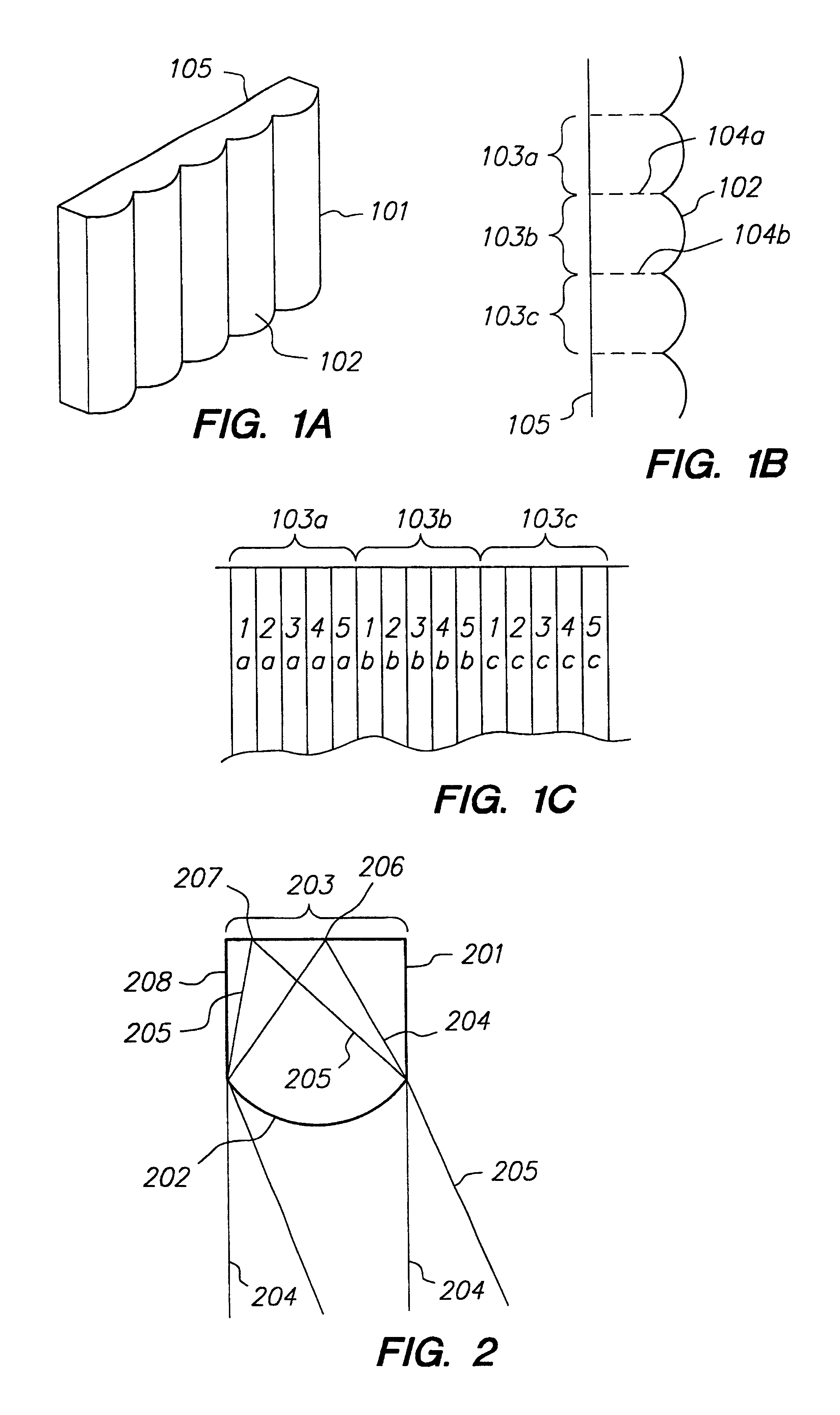
FIG. 1A is a perspective view of a parallax panoramagram, also known as a lenticular stereogram, having a lenticular screen 101 and its associated print image 105. Screen 101 is comprised of individual cylindrical lenticules 102. The front surface of the print 105 is in intimate juxtaposition with the back of the lenticular screen 101. The optics and organization of lenticular displays are generally well known to those in the art and are therefore not described in any detail. Our discussion is confined to descriptions that are relevant to the improvement of depth and sharpness disclosed herein.

FIG. 1B is a top view of the lenticular screen 101 and associated print surface 105 of FIG. 1A. The dotted lines 104a and 104b are for reference only and are perpendicular to the print surface 105. These lines 104a and 104b are meant to indicate the area under a particular lenticule which is devoted to the image that is specifically associated with that lenticule. Brackets 103a, 103b and 103c ...


PUM


Abstract

A parallax panoramagram has increased depth and sharpness when a sharpness filter is applied after interdigitation of multiple image portions. An optical path of wave train (204) (on-axis) and wave train (205) (off-axis) intersect a single lenticle (201). The lenticle has a focal length (208) and the on-axis (204) and off-axis (205) wave trains correspond to different stripes. These wave trains (204 and 205) comme to focus at points (206 and 207) respectively. The surface (202) has a cylindrical curvature, and bracket (203) denotes the width of the lenticle (201). Each eye of the observer sees its own perspective view when looking at a lenticular stereogram.

Description

FIELD OF THE INVENTIONThis invention relates to parallax panoramagrams, also known as lenticular stereograms, and more particularly, to a method for increasing the depth and sharpness of images in lenticular stereograms.BACKGROUND OF THE INVENTIONFor many decades, inventors have studied and attempted to improve the lenticular stereogram, also known as the parallax panoramagram. The art has been very well traveled and is very well understood. By incorporating a cylindrical lenticular screen, corduroy-like, over the surface of a properly encoded print, a stereoscopic depth effect may be achieved. As shown in FIG. 1, the lenticules 102 have semi-cylindrical surfaces aligned so that their length is in the vertical direction. The lenticules are in intimate juxtaposition with a print surface 105, which contains columns of encoded visual information. Each column is associated with a particular lenticule, and within each column there will be found a series of views ranging from a leftmost t...

Claims


Application Information

Patent Timeline
IPC IPC(8): G02B27/22G02B30/27
CPCG02B27/2214G02B30/27
Inventor LIPTON, LENNYDORWORTH, BRUCEAKKA, ROBERT
Owner LEDOR LLC
Why Eureka
Try Eureka