
Airborne mine neutralization system, neutralizer pressure relief valve

a mine neutralization system and pressure relief valve technology, applied in special-purpose vessels, underwater equipment, mine-sweeping, etc., can solve the problems of inability to use an undersea vehicle, large amount of li/so/sub>2 /sub>vapor,

Inactive Publication Date: 2005-02-08
THE UNITED STATES OF AMERICA AS REPRESENTED BY THE SECRETARY OF THE NAVY
View PDF3 Cites 3 Cited by
  • Summary
  • Abstract
  • Description
  • Claims
  • Application Information

AI Technical Summary

Benefits of technology

The invention is a pressure relief valve system for an undersea vehicle that contains lithium batteries. The system has two pressure relief valves that are connected to the interior of the vehicle and can vent pressurized gas from the batteries to the ambient. The valves are mounted on pylons on the vehicle and have a valve plug with a wire and O-ring that can displace the plug to release the pressure when the gas pressure exceeds a certain level. The system is reliable and can withstand high depths. The technical effects of the invention are to provide a safe and effective way to release pressure from undersea vehicles with lithium batteries, and to prevent damage to the batteries from over-charging or over-heating.

Problems solved by technology

One of the major consequences of using high power density lithium batteries, however, is that they can produce considerable amounts of pungent and toxic Li / SO2 vapors at temperatures above their venting point of about 200° F. Such temperatures could be created in the event of a shipboard fire in either the magazine where the submersibles are stored or in an adjacent compartment.
Irrespective of the advantages of having a lithium battery power source aboard, the undersea vehicle could not be used until this damage was repaired.

Method used


Image

  • Airborne mine neutralization system, neutralizer pressure relief valve
  • Airborne mine neutralization system, neutralizer pressure relief valve
  • Airborne mine neutralization system, neutralizer pressure relief valve

Examples


Embodiment Construction

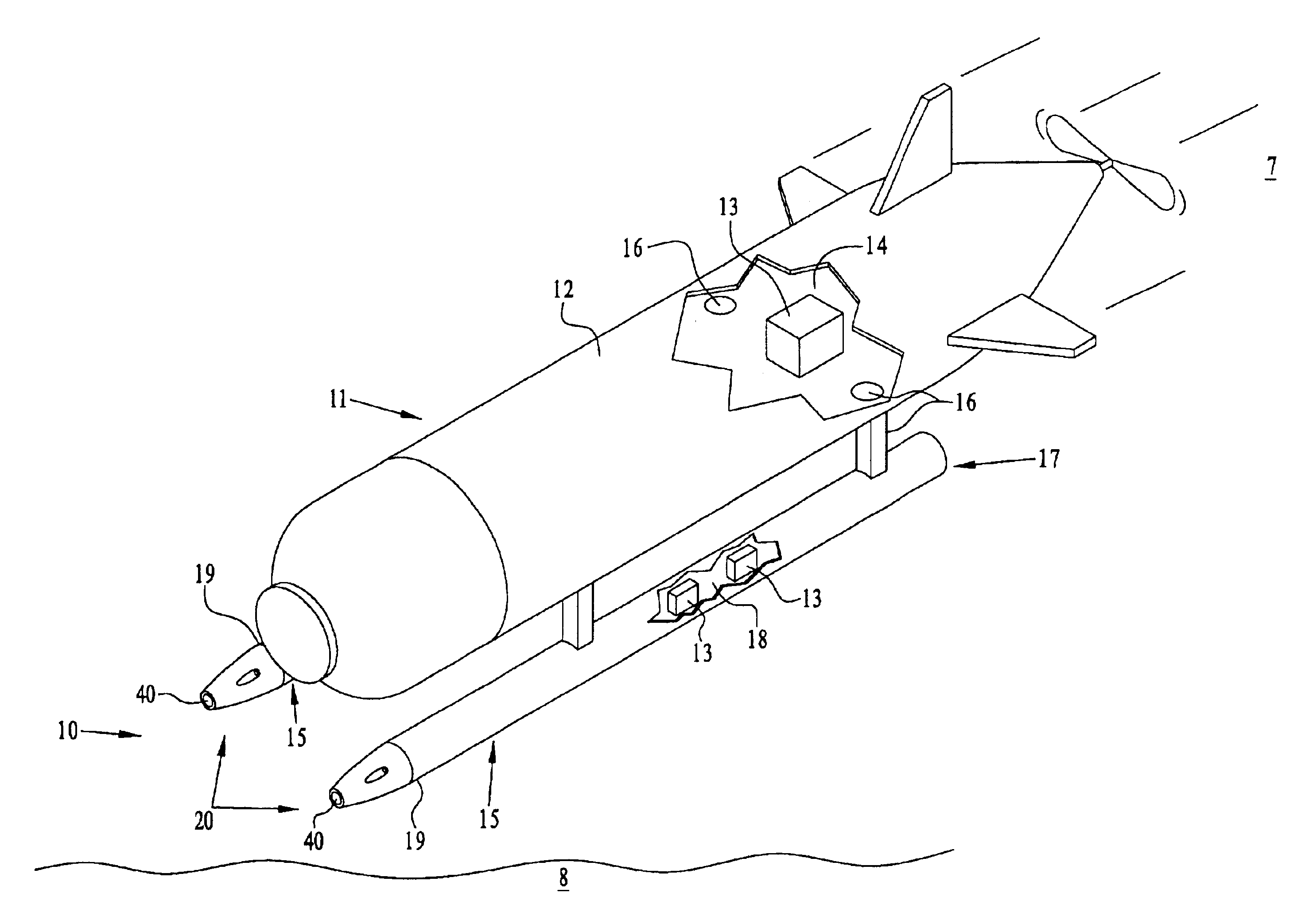
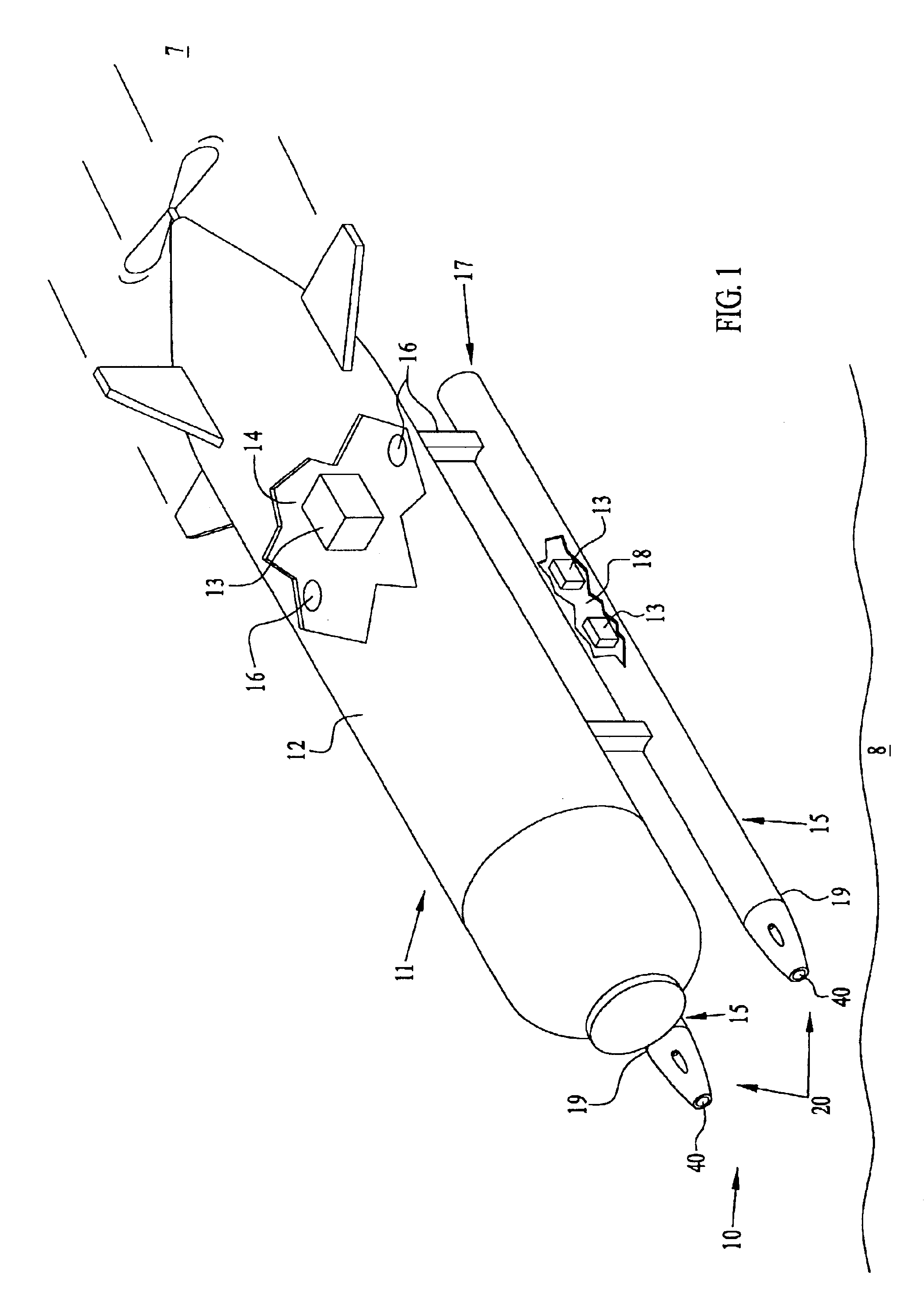
Referring to FIG. 1, pressure relief valve system 10 of the invention vents gases from an unmanned undersea vehicle 11 that could otherwise build in pressure and possibly compromise the integrity of a pressure hull 12. Undersea vehicle 11 can rapidly transit underwater and can be dropped through air 7 from an aircraft (not shown). Vehicle 11 is capable of diving to considerable depths in water 8, in excess of five hundred feet. Undersea vehicle 11 has lithium batteries 13 in an interior 14 in hull 12 and / or in a pair of hollow pylons 15 located outside of and below hull 12.

An open duct 16 extends from the aft part 17 of each hollow pylon 15 to fluidly communicate with interior 14. Ducts 16 could couple harmful levels of pressurized vapors, or gas either to or from interior 14. This pressurized gas can include Li / SO2 vapors as well as other vapors from other types of lithium batteries having other lithium chemistries. If batteries 13 are not contained in pylons 15 but are only in int...


PUM


Abstract

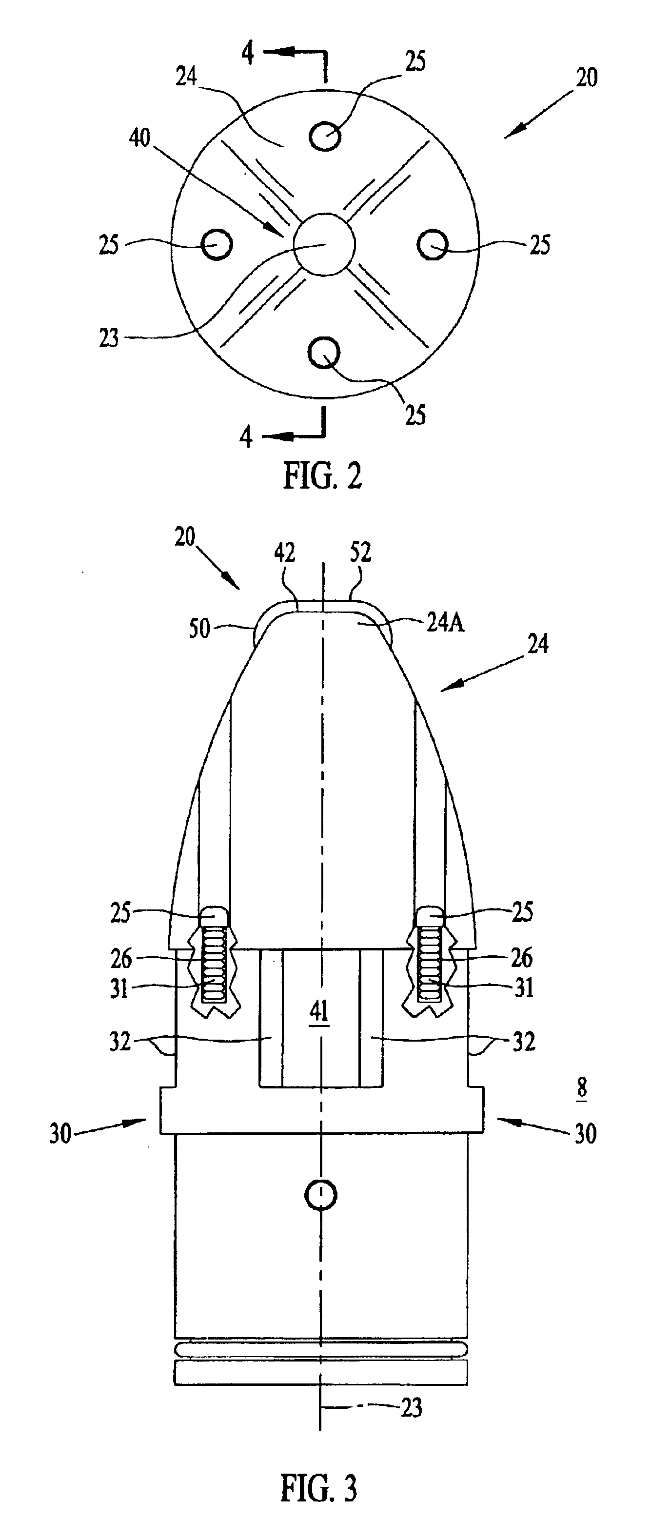
A combination pressure relief valve system and undersea vehicle vents pressurized gas from lithium batteries to ambient. An undersea vehicle having an interior has a pair of hollow pylons each having a passageway fluidly communicating with the interior. A pressure relief valve is mounted on each pylon, and each pressure relief valve has a body portion having an inner bore fluidly communicating with a passageway. An elongate valve plug in the body portion is interposed between each passageway and ambient and the valve plug has a lateral bore and a circumferentially disposed O-ring. A nose portion is secured to the body portion, and the nose portion has a pair of laterally aligned bores aligned with the lateral bore of the elongate valve plug. A wire extends through the laterally aligned bores and lateral bore. The O-ring and wire retain the valve plug interposed between a passageway and ambient.

Description

BACKGROUND OF THE INVENTIONThis invention relates to a safety device for an undersea vehicle using lithium batteries. More particularly, this invention is to a pressure relief valve system for venting Li / SO2 vapors created by lithium batteries to prevent damage to an undersea vehicle.The long shelf-life and higher watt-hours per unit volume of lithium batteries as compared to other contemporary batteries is well known. Marine designers have included lithium batteries in unmanned submersibles where a compact high-power electrical source is needed to produce sufficient power for prolonged operations at considerable depth.One of the major consequences of using high power density lithium batteries, however, is that they can produce considerable amounts of pungent and toxic Li / SO2 vapors at temperatures above their venting point of about 200° F. Such temperatures could be created in the event of a shipboard fire in either the magazine where the submersibles are stored or in an adjacent c...

Claims


Application Information

Patent Timeline
Patent Type & Authority Patents(United States)
IPC IPC(8): B63G8/00B63G8/36F16K17/02F16K17/00F16K17/40B63G7/00B63G7/02
CPCB63G8/001F16K17/406F16K17/02B63G8/36B63G7/02
Inventor PRUITT, THOMASGEORGIADIS, DANIELPAPCIAK, JOSEPH
Owner THE UNITED STATES OF AMERICA AS REPRESENTED BY THE SECRETARY OF THE NAVY
Learn More