Method and apparatus for insuring integrity of a connectorized antenna

a technology of connectorized antennas and antennas, applied in the field of communication devices, can solve the problems of difficult or impossible for users to attach antennas that are not intended for use with devices, and achieve the effect of verifying the integrity of antennas

Inactive Publication Date: 2005-02-08
QUALCOMM INC
View PDF16 Cites 254 Cited by
  • Summary
  • Abstract
  • Description
  • Claims
  • Application Information

AI Technical Summary

Benefits of technology

The present inventors have realized the need to verify antenna integrity, and particularly connectorized antennas, so it can be assured that characteristics of an antenna match other components (receiver, power, etc) of a communications system to which they are attached. The present invention verifies the integrity of an antenna not by a unique physical connector, but by a unique electrical property that can be hidden within the antenna itself. Depending on the sophistication of the integrity algorithm, it can be made very difficult or impossible for a user to attach an antenna that is not intended for use with the device. Further, it would be possible for the device to read information from the antenna such as the antennas gain. After reading the gain of the antenna, the device could automatically adjust its transmit power to insure FCC compliance.
The invention includes a method of checking integrity of an antenna, comprising the steps of, determining at least one property of the antenna, enabling an electronic device connected to the antenna if the antenna property is within a valid range. The invention also includes a method of manufacturing an antenna, comprising the steps of, preparing a substrate, disposing at least one antenna element on the substrate, attaching a connector to said at least one antenna element, inserting at least one electronic component on the substrate in a location where it is not easily removed or modified. To increase robustness, the antenna element may be disposed within the substrate.

Problems solved by technology

Depending on the sophistication of the integrity algorithm, it can be made very difficult or impossible for a user to attach an antenna that is not intended for use with the device.

Method used


Image

  • Method and apparatus for insuring integrity of a connectorized antenna
  • Method and apparatus for insuring integrity of a connectorized antenna
  • Method and apparatus for insuring integrity of a connectorized antenna

Examples


Embodiment Construction

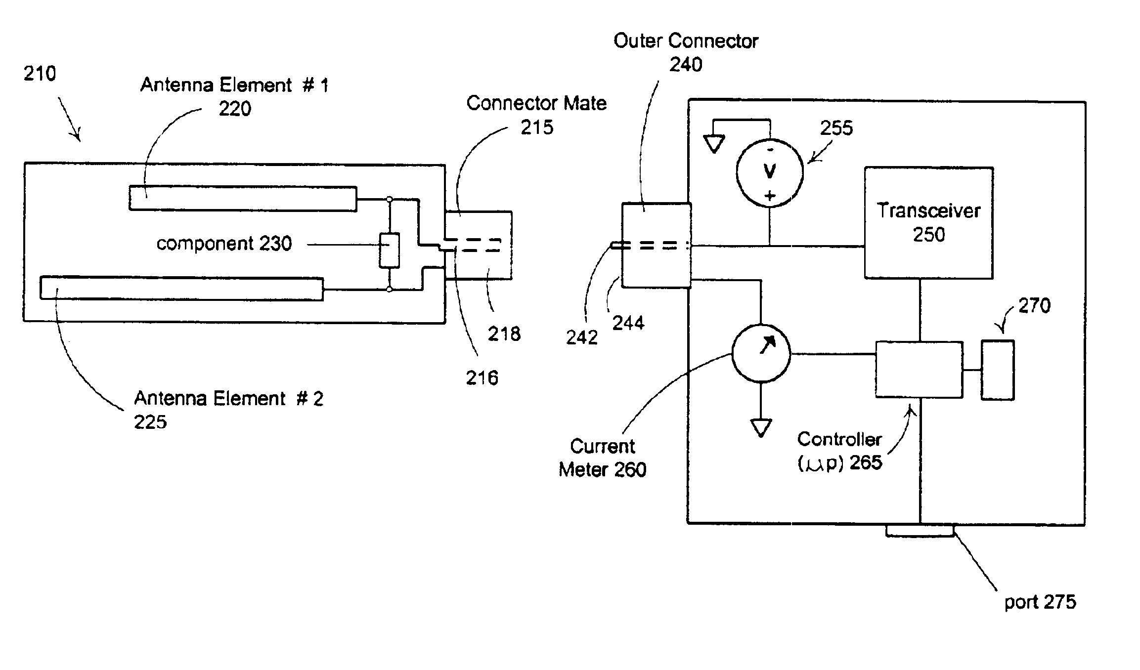
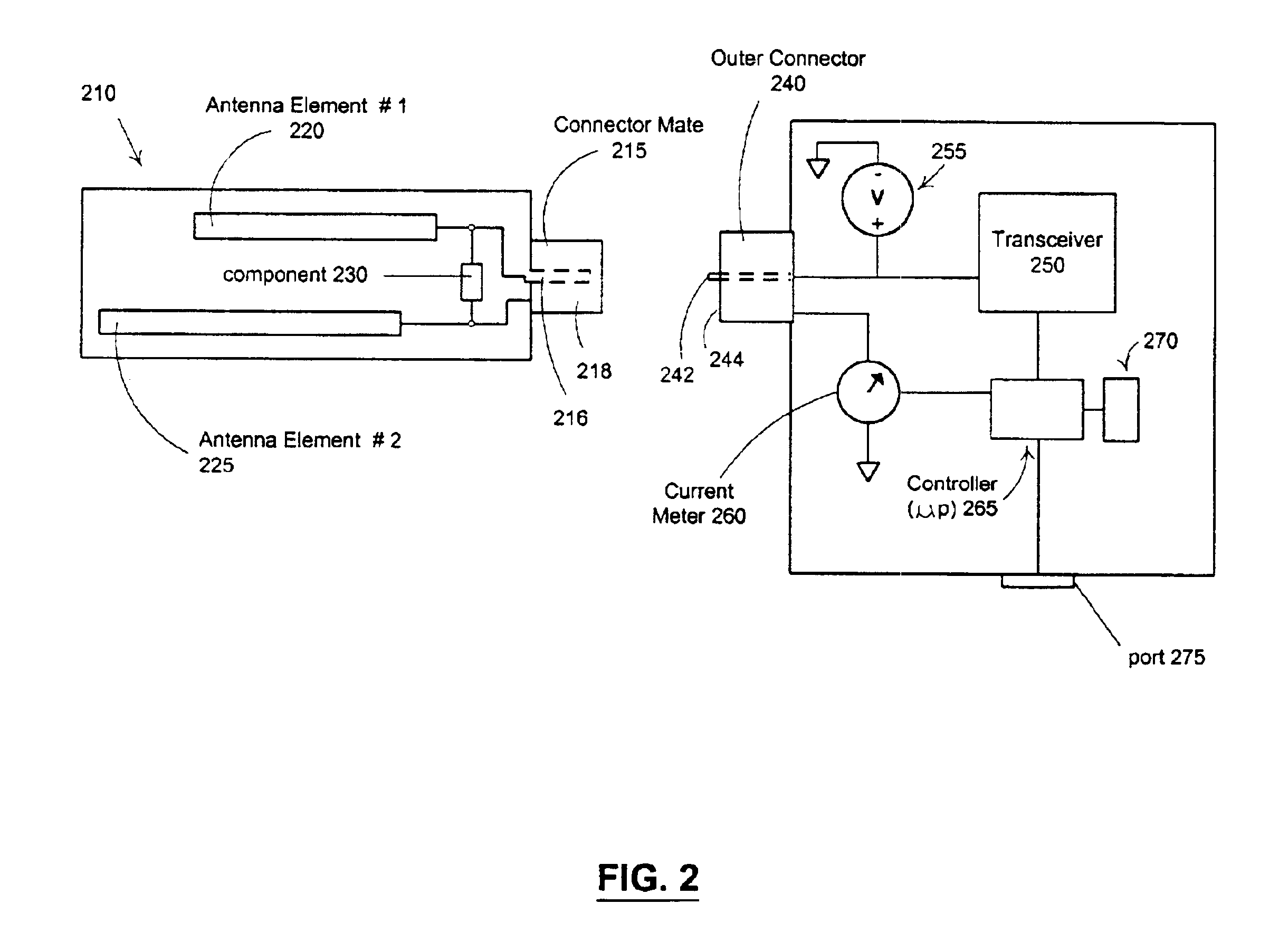
The present inventors have realized the need to provide connectorized antennas whose integrity can be verified as matching the other components of a communications system to which they are attached. As stated above, there are a number of reasons that manufacturers prefer to have antennas that are connectorized. Therefore, it would seem advantageous to make all antennas connectorized so that they can be easily mixed and matched for repairs, testing, experimentation, etc. However, because there are a number of reasons that not just any antenna should be allowed to be attached and operate with a given communications system, the present invention provides a device and method that insures that a given communication device will only operate when antennas that are appropriate for that device are connected.

In one embodiment, the present invention comprises a resistor having a specific value that identifies one or more property or characteristic of the antenna. The resistor is installed on t...


PUM


Abstract

An antenna is provided with an electronic component or circuit that has a value corresponding to properties of the antenna. A read mechanism reads the value and sets an operational status of a transceiver based on the value. In one embodiment, electronic component is a resistor having a value that identifies the antenna properties. A table may be used to correlate resistor values to different types of antennas or sets of antenna properties. Alternatively, the circuit can be embodied in a microchip that provides a response to a challenge sent by the read mechanism. The response encodes the properties of the antenna. The encoding scheme includes values from the challenge. Alternatively, the response is a code that is indexed into a table of antenna properties. In one embodiment, the antenna is connectorized.

Description

COPYRIGHT NOTICEA portion of the disclosure of this patent document contains material which is subject to copyright protection. The copyright owner has no objection to the facsimile reproduction by anyone of the patent document or the patent disclosure, as it appears in the Patent and Trademark Office patent file or records, but otherwise reserves all copyright rights whatsoever.BACKGROUND OF THE INVENTION1. Field of InventionThe present invention relates to communication devices, and more particularly to wireless devices. The present invention is also related to checking integrity of devices connected to wireless devices, and particularly to checking integrity and verification of proper antenna devices connected to wireless communication devices.2. Discussion of BackgroundThere are a number of reasons that manufacturers prefer to have antennas that are connectorized. This allows customers to choose among a variety of antennas, select the best one for a given situation, and attach t...

Claims


Application Information

Patent Timeline
Patent Type & Authority Patents(United States)
IPC IPC(8): H01Q1/38H01Q9/04H01Q9/06H01Q1/24H01R13/703H01R13/70
CPCH01Q1/242H01R13/7039H01Q9/065H01Q1/38
Inventor MCFARLAND, WILLIAM J.GREEN, MICHAEL R.
Owner QUALCOMM INC
Why Eureka
Try Eureka