Load pump with an extremely wide output voltage

Inactive Publication Date: 2005-02-08
ALCATEL LUCENT SAS
View PDF6 Cites 32 Cited by
  • Summary
  • Abstract
  • Description
  • Claims
  • Application Information

AI Technical Summary

Benefits of technology

Consequently, the aim of the present invention is to overcome the above-mentioned drawbacks of the prior art and therefore proposes providing a load pump able to operate with a wide output voltage range so as to supply a constant current which i

Problems solved by technology

Now in special operating conditions, a problem is likely to appear.
Thus, this requirement of the prior art prevents functioning with small mains voltages.
In fact, in this case, a low mains voltage less than said mains voltage would result in a bad recopy of the currents since it is then not possible to place the transistors in a good working condition, namely the saturated state which is characterised b

Method used


Image

  • Load pump with an extremely wide output voltage
  • Load pump with an extremely wide output voltage

Examples


Example

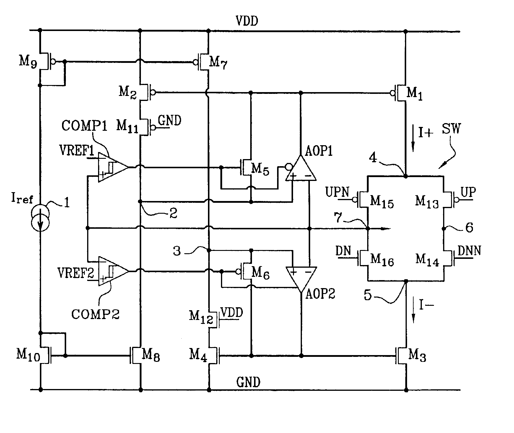
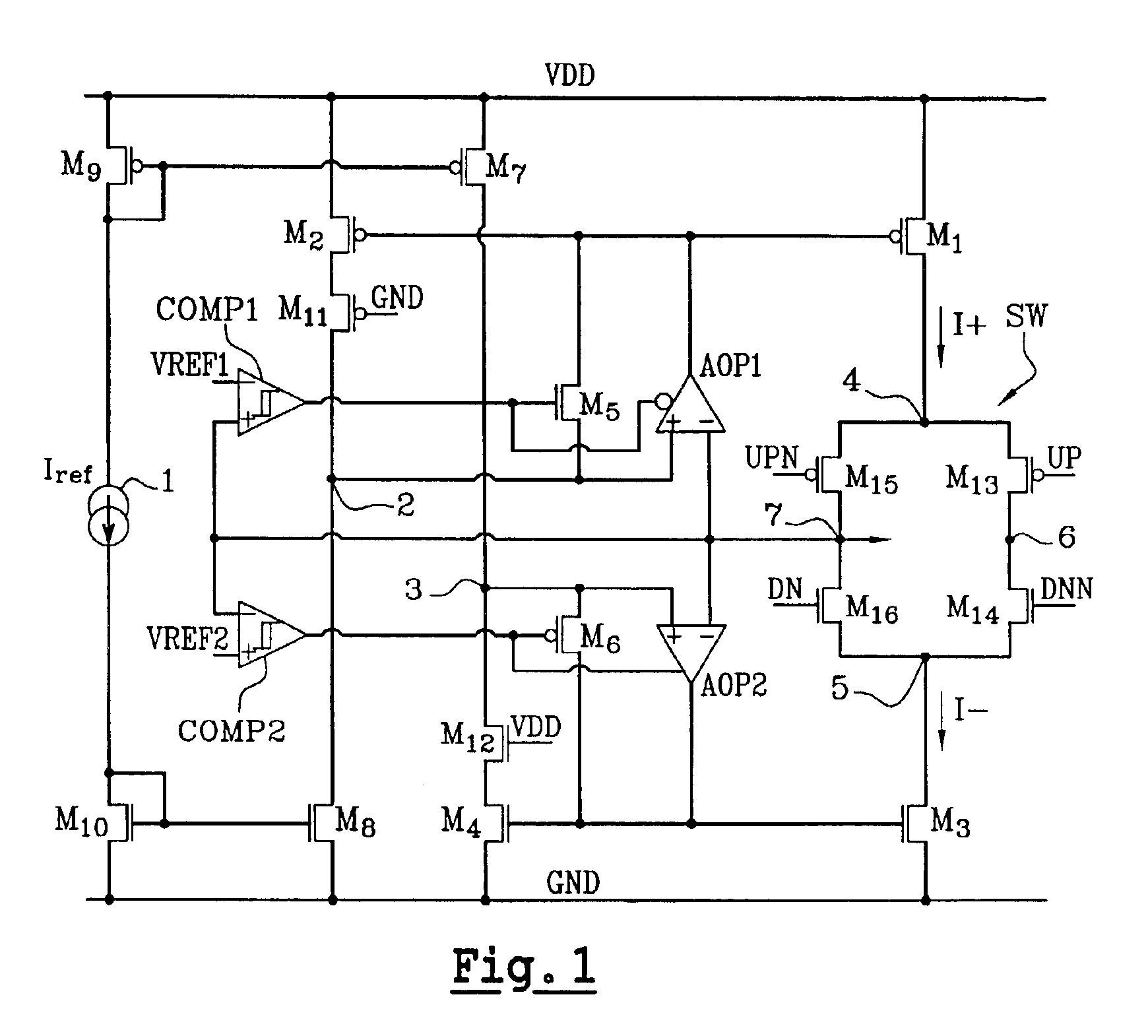
FIG. 1 thus describes a load pump according to the invention which more specifically consists of a bidirectional current source polarised between the feed voltage VDD and the ground GND. The bidirectional current source forming the load pump is embodied according to the CMOS (“Complementary Metal Oxide Semiconductor”) technique.

The load pump comprises a first branch formed by a type P diode-mounted MOS transistor M9, a current feed 1 generating a reference current Iref and a type N diode-mounted MOS transistor, all connected in series.

A second branch is formed by a first MOS transistor M8, a second MOS transistor M11 with an intermediate node 2 between them and a third MOS transistor M2 for recopying the current, all being connected in series. The transistor M2 is mirrored with a MOS transistor MI forming the positive current source.

Thus, the source of the transistor MB is connected to the ground GND and its control grid is connected to the control grid of the diode-mounted MOS tran...


PUM


Abstract

The invention concerns a load pump device able to provide a constant current, respectively positive or negative, over an extremely wide output voltage range. A symmetrical switching system activates a first operational amplifier (AOP1) associated with the positive current source or a second amplifier (AOP2) associated with the negative current source according to predetermined threshold values (Vref), the first amplifier being provided so as to restore the behavior of the current mirror (M2, M1) generating a positive current when the output voltage of the device approaches the feed voltage (VDD) and the second amplifier being provided so as to restore the behavior of the current mirror (M4, M3) generating a negative current when the output voltage of the device approaches the earth (GND), thus allowing the output current of the device to be always constant and equal to a reference value (Iref).

Description

FIELD OF THE INVENTIONThe present invention concerns a load pump able to function with an extremely wide output voltage range spread between the ground and the mains voltage.This load pump of the invention is in particular able to maximise the adjustment range of a voltage-controlled oscillator of an automatic control phase loop and thus can be advantageously applied in radioelectric transmission systems.BACKGROUND OF THE INVENTIONA load pump is a device normally used in automatic control phase loops and is more specifically placed between the phase comparator and the loop filter. The automatic control phase loop or PLL (“phase locked loop”) in fact denotes an assembly formed of an automatic controlled phase oscillator and the associated phase comparator and filter.The phase automatic controlled oscillator is provided to provide a signal whose phase is triggered to that of a reference signal. This concerns a voltage-controlled oscillator whose output signal is applied to a phase com...

Claims


Application Information

Patent Timeline
IPC IPC(8): H03L7/089H03L7/08
CPCH03L7/0896
Inventor DESORTIAUX, VINCENT
Owner ALCATEL LUCENT SAS
Why Eureka
Try Eureka