Power converter and driving method for the same

A technology of power converter and driving voltage, which is applied in the direction of output power conversion devices, instruments, electric light sources, etc., can solve problems such as the inability to emit a constant level of light, and the inability of LED lighting power converters to control current.

Inactive Publication Date: 2016-03-23
SAMSUNG ELECTRO MECHANICS CO LTD
View PDF1 Cites 0 Cited by
  • Summary
  • Abstract
  • Description
  • Claims
  • Application Information

AI Technical Summary

Problems solved by technology

At the same time, when the Vf of the LED module is not within the stated range, the LED lighting power converter cannot control the current and therefore cannot emit a constant level of light

Method used


Image

  • Power converter and driving method for the same
  • Power converter and driving method for the same
  • Power converter and driving method for the same

Examples


Embodiment Construction

[0015] Reference will now be made in detail to various embodiments, examples of which are illustrated in the accompanying drawings. In the following detailed description, numerous specific details are disclosed in order to provide a thorough understanding of the present disclosure. It will be apparent, however, to one skilled in the art that the present disclosure may be practiced without these specific details. In other instances, well-known methods, procedures, systems, and components have not been described in detail so as not to obscure aspects of the various embodiments.

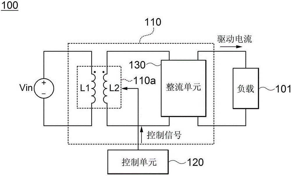
[0016] figure 1 is a block diagram of a power converter according to an embodiment of the present disclosure.

[0017] Such as figure 1 As shown, the power converter 100 includes a first coil L1 and a second coil L2. The power converter 100 also includes a power supply unit 110 and a control unit 120 . The power supply unit 110 applies a driving voltage to the load 101, wherein the magnitude of the...


PUM


Abstract

The present invention provides a power converter and a driving method for the same. The power converter includes: a power supply unit provided with a first coil and a second coil and configured to apply a driving voltage to a load, the power supply unit being configured to adjust a magnitude of the driving voltage in response to a turn ratio of the first coil to the second coil; and a control unit configured to output a control signal for control the turn ratio of the first coil to the second coil based on the magnitude of the driving voltage.

Description

[0001] This application claims the benefit of foreign priority from Korean Patent Application No. 10-2014-0121901 filed with the Korean Intellectual Property Office on September 15, 2014, which is hereby incorporated by reference in its entirety. technical field [0002] Embodiments of the present invention relate to a power converter and a driving method thereof. Background technique [0003] Typically, power converters for LED lighting control the current applied to the LED modules at a constant level, thereby maintaining a constant level of brightness. To this end, LED lighting power converters use methods such as pulse width modulation (PWM, PulseWidthModulation) or pulse frequency modulation (PFM, PulseFrequencyModulation). For an LED module, the LED forward voltage (Vf) is determined according to the number of LEDs connected in parallel and / or in series with each other and the power consumption of each LED. Furthermore, LED lighting power converters have a limited ran...

Claims


Application Information

Patent Timeline
IPC IPC(8): H02M3/335H05B37/02H05B44/00
CPCH02M1/10H02M3/33507H05B45/00H05B47/10
Inventor 金玟辰崔丁文金起弘
Owner SAMSUNG ELECTRO MECHANICS CO LTD
Why Eureka
Try Eureka