MEMS optical switch with thermal actuator

Inactive Publication Date: 2005-02-08
THE UNITED STATES OF AMERICA AS REPRESENTED BY THE SECRETARY OF THE NAVY
View PDF6 Cites 75 Cited by
  • Summary
  • Abstract
  • Description
  • Claims
  • Application Information

AI Technical Summary

Benefits of technology

It is another object of the invention to provide an optical switch wherein the optical fibe

Problems solved by technology

Due to design and fabrication limitations, these switches are often very optically inefficient.
The surfaces used for micro-optical mirrors often are not very reflective and the input and output fibers must be placed at great distances

Method used


Image

  • MEMS optical switch with thermal actuator
  • MEMS optical switch with thermal actuator
  • MEMS optical switch with thermal actuator

Examples


Embodiment Construction

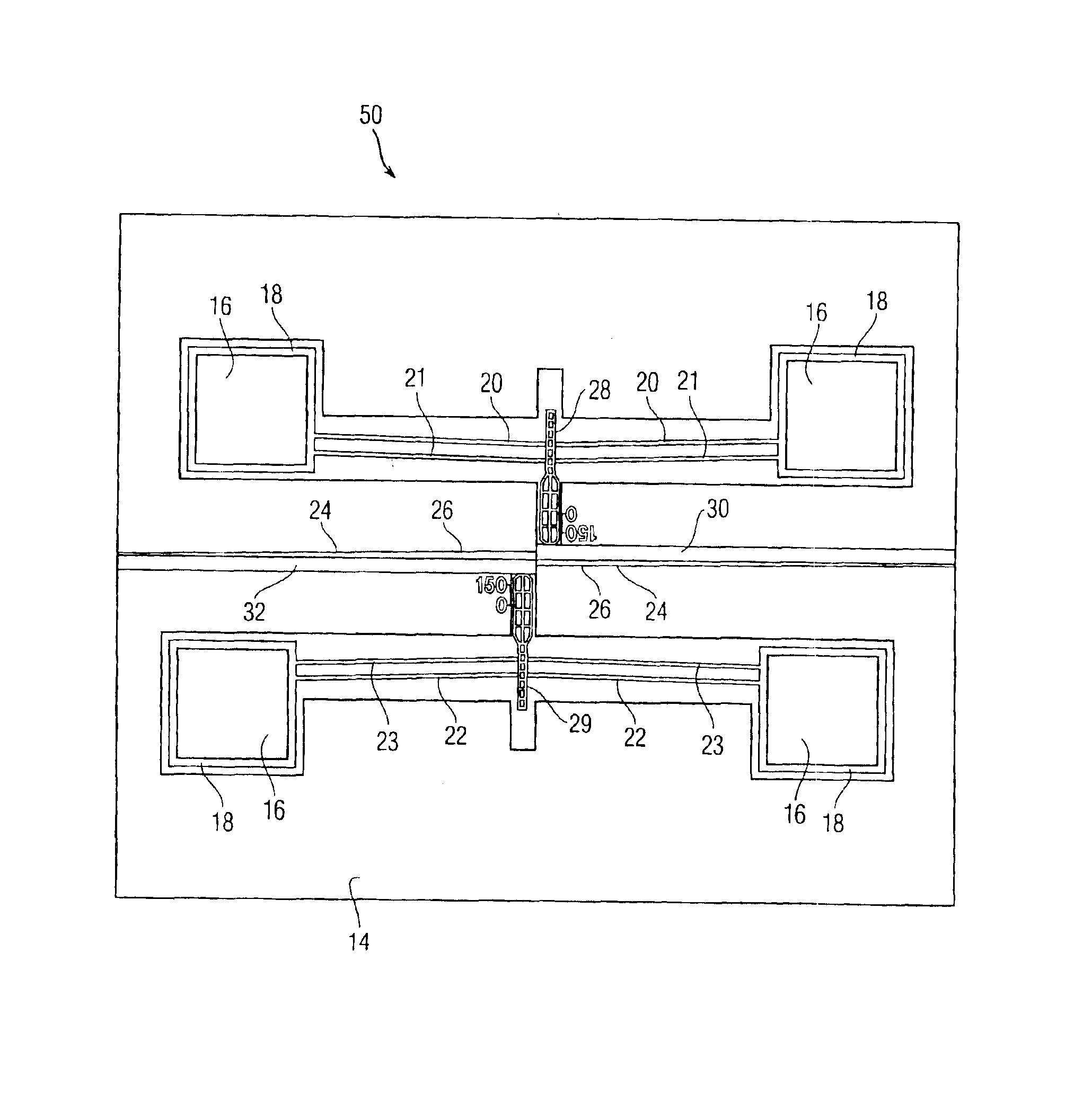
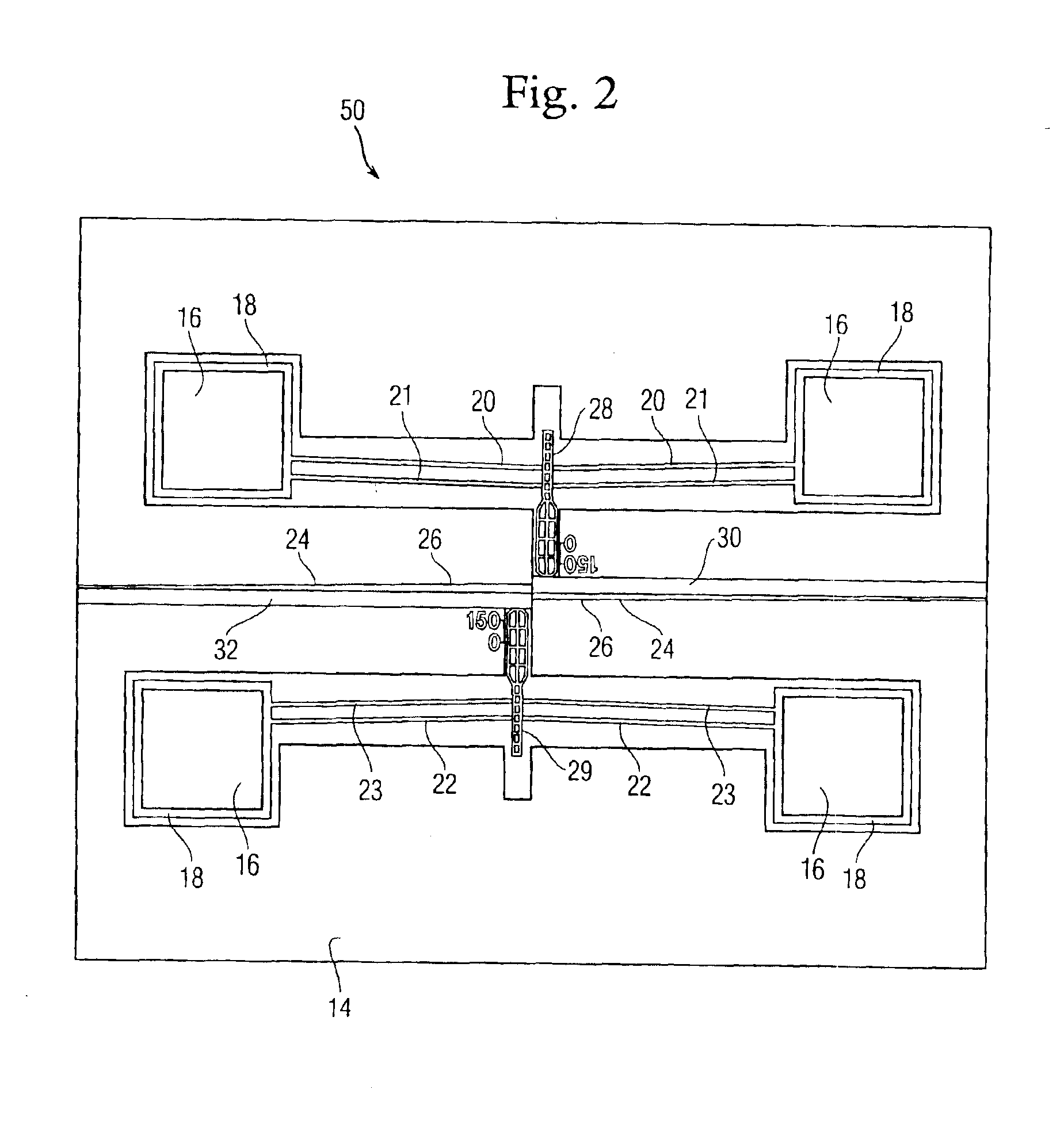
In a moving fiber type optical switch, two optical fibers are placed in alignment channels on a chip surface. The optical fibers face each other and can be offset, depending on whether or not optical power transfer is desired in the unpowered state. An actuator for at least one of the optical fibers acts to push the fibers in or out of line with each other so that optical switching takes place.

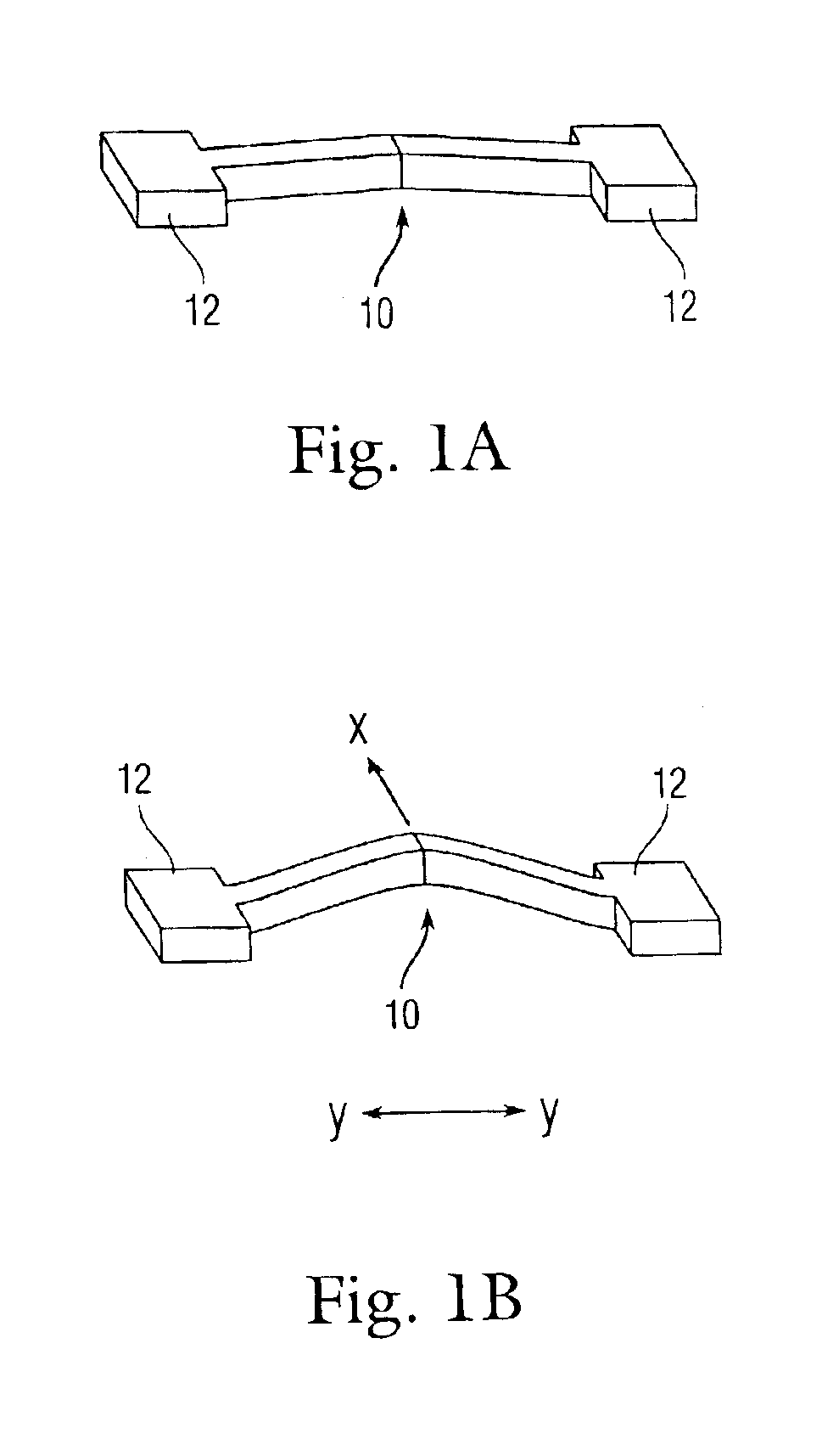
FIGS. 1A and 1B illustrate the principle of operation of a v-beam thermal actuator. FIG. 1A is a perspective view of a v-beam 10 in an off state. FIG. 1B is a perspective view of the v-beam 10 of FIG. 1A in an on state. FIG. 1A shows a v-beam 10 connected at its ends to anchors 12. When an electrical current is applied to the v-beam 10 through the anchors 12, the v-beam increases in temperature because of resistance heating. The rising temperature of the v-beam 10 causes it to expand in the y-direction shown in FIG. 1B. However, because the v-beam is constrained by the anchors 12 in the y-dire...


PUM


Abstract

A MEMS type optical switch includes a substrate, the substrate including at least one groove formed therein; first and second optical fibers disposed in the at least one groove, the at least one groove including a widened portion for movement of at least one of the first and second optical fibers; a thermal actuator disposed adjacent one of the first and second optical fibers, the thermal actuator comprising at least one v-beam, a pair of anchors connected to ends of the v-beam, and a yoke disposed in a central portion of the v-beam.

Description

BACKGROUND OF THE INVENTIONThe invention relates in general to microelectromechanical systems (MEMS) type optical switches and in particular to a MEMS optical switch using a thermal actuator.Optical MEMS is a fairly new subject with many switch designs appearing in the past 5-6 years. Most MEMS optical switches work by actuating a slider in and out of the optical path between one or several input and output optical fibers. The slider acts in one of two ways. First, it could serve to block the light from entering the output optical fiber. Second, the slider could contain a reflector the redirects the light to the output fiber. Due to design and fabrication limitations, these switches are often very optically inefficient.Many of these limitations can be overcome by directly actuating the input and / or output optical fibers in and out of line with each other to make for more efficient optical transfer. The major advantage of the moving fiber type optical switch is that the optical effic...

Claims


Application Information

Patent Timeline
IPC IPC(8): G02B6/35
CPCG02B6/3576G02B6/3508G02B6/3552G02B6/3594G02B6/358G02B6/3584
Inventor COCHRAN, KEVIN
Owner THE UNITED STATES OF AMERICA AS REPRESENTED BY THE SECRETARY OF THE NAVY
Why Eureka
Try Eureka