Camera system for providing instant switching between wide angle and full resolution views of a subject

Inactive Publication Date: 2005-02-08
KONINKLIJKE PHILIPS ELECTRONICS NV
View PDF9 Cites 35 Cited by
  • Summary
  • Abstract
  • Description
  • Claims
  • Application Information

AI Technical Summary

Benefits of technology

In an alternate embodiment, the camera system of the present invention does not effect generation of data defining the desired subject. Instead,

Problems solved by technology

Furthermore, the resolution of the image of the EPTZ camera is significantly reduced when attempting to upscale a small region of interest to a relatively lar

Method used


Image

  • Camera system for providing instant switching between wide angle and full resolution views of a subject
  • Camera system for providing instant switching between wide angle and full resolution views of a subject

Examples


Embodiment Construction

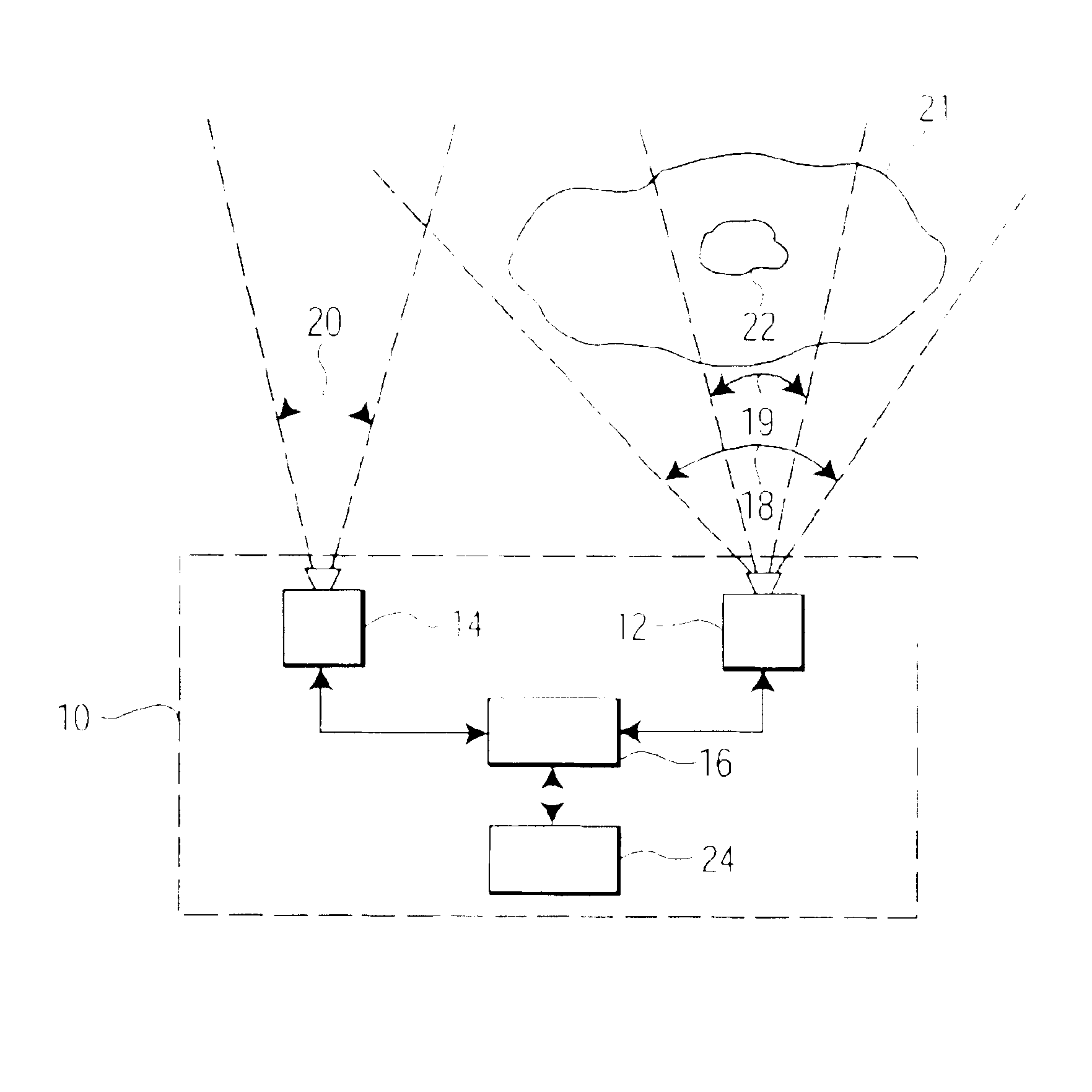
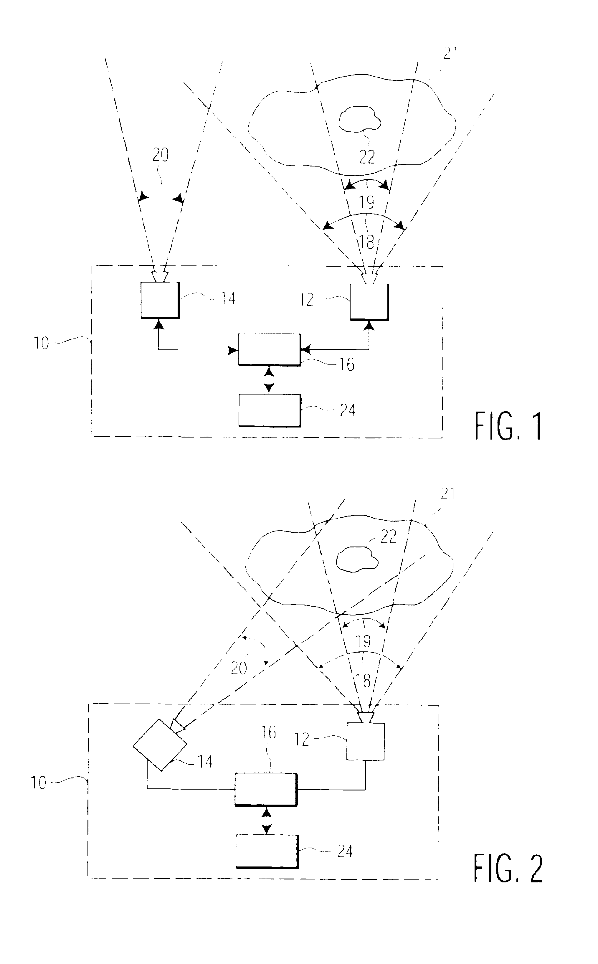
Referring to FIG. 1, camera system 10 of the present invention generally comprises stationary camera 12, remotely controllable camera 14 and programmable processor 16. In one embodiment, stationary camera 12 comprises an electronic-pan-tilt-zoom (“EPTZ”) camera. In one embodiment, camera 14 comprises a mechanical-pan-tilt-zoom (“MPTZ”) camera. Cameras 12 and 14 are controlled by processor 16. Specifically, processor 16 issues commands that can cause camera 12 to electronically pan, tilt, zoom and focus as well as other camera functions. Remotely controllable camera 14 comprises motors (not shown) which effect pan, tilt, zoom and focus functions. The aforementioned motors are controlled by control signals outputted by processor 16. In one embodiment, processor 16 comprises a computer. One such computer is described in U.S. Pat. No. 5,434,617, the disclosure of which is incorporated herein by reference. Stationary camera 12 is configured to provide wide angle view 18. Remotely control...


PUM


Abstract

A camera system and method for operating that system. The camera system comprises a stationary camera having a wide angle view, a remotely controllable camera having a relatively smaller angle view for providing images in substantially full resolution, and a processor. The processor monitors the wide angle view of the stationary camera, receives information concerning a selected desired subject within the wide angle view, generates an electronic pan-tilt-zoom view of the selected desired subject based on the wide angle view of the stationary camera, controls the remotely controllable camera for providing a view that overlaps the electronic pan-tilt-zoom view of the desired subject, and processes the electronic pan-tilt-zoom view of the desired subject in accordance with the resolution of the remotely controllable camera.

Description

BACKGROUND OF THE INVENTION1. Field of the InventionThe present invention generally relates to a camera system and a method for operating same.2. Description of Prior ArtIn a conventional mechanical pan / tilt / zoom camera system, when a new region of interest is identified, a computer moves the manual camera to view that region and controls the zoom function of the camera in order to frame the new region of interest. On the other hand, conventional electronic-pan-tilt-zoom (“EPTZ”) cameras remain stationary, but the region of interest is culled from the overall image and scaled to fit the display window. Furthermore, the resolution of the image of the EPTZ camera is significantly reduced when attempting to upscale a small region of interest to a relatively larger display. Although MPTZ cameras can provide a full resolution view of the desired region of interest, MPTZ cameras cannot immediately move to the next shot.It is therefore an object of the present invention to provide a camera...

Claims


Application Information

Patent Timeline
IPC IPC(8): H04N7/18H04N5/225G03B5/00G03B5/06G03B15/00G03B17/00H04N5/232
CPCG08B13/19628H04N7/181H04N5/2259G08B13/19643H04N23/58
Inventor PELLETIER, DANIEL
Owner KONINKLIJKE PHILIPS ELECTRONICS NV
Why Eureka
Try Eureka