Automatic calibration of PTZ camera system

a technology of automatic calibration and camera system, which is applied in the field of automatic acquisition of calibration parameters of ptz camera, can solve the problems of not always being able to capture high-resolution images, difficult to reach deployed ptz camera in need of calibration, and rendering manual calibration impractical

Active Publication Date: 2013-03-26
MOTOROLA SOLUTIONS INC
View PDF5 Cites 17 Cited by
  • Summary
  • Abstract
  • Description
  • Claims
  • Application Information

AI Technical Summary

Problems solved by technology

However, while stationary camera systems provide a wide coverage area, they typically do not capture high resolution images.
While manual calibration of the PTZ camera is desirable, it may not always be possible.
For example, a deployed PTZ camera in need of calibration may be difficult to reach rendering manual calibration impractical.

Method used


Image

  • Automatic calibration of PTZ camera system
  • Automatic calibration of PTZ camera system
  • Automatic calibration of PTZ camera system

Examples


Embodiment Construction

[0044]Exemplary embodiments of the invention are discussed in detail below. While specific exemplary embodiments are discussed, it should be understood that this is done for illustration purposes only. In describing and illustrating the exemplary embodiments, specific terminology is employed for the sake of clarity. However, the invention is not intended to be limited to the specific terminology so selected. A person skilled in the relevant art will recognize that other components and configurations may be used without parting from the spirit and scope of the invention. It is to be understood that each specific element includes all technical equivalents that operate in a similar manner to accomplish a similar purpose. Each reference cited herein is incorporated by reference. The examples and embodiments described herein are non-limiting examples.

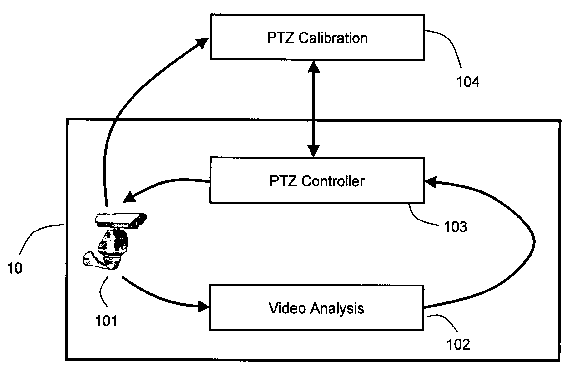
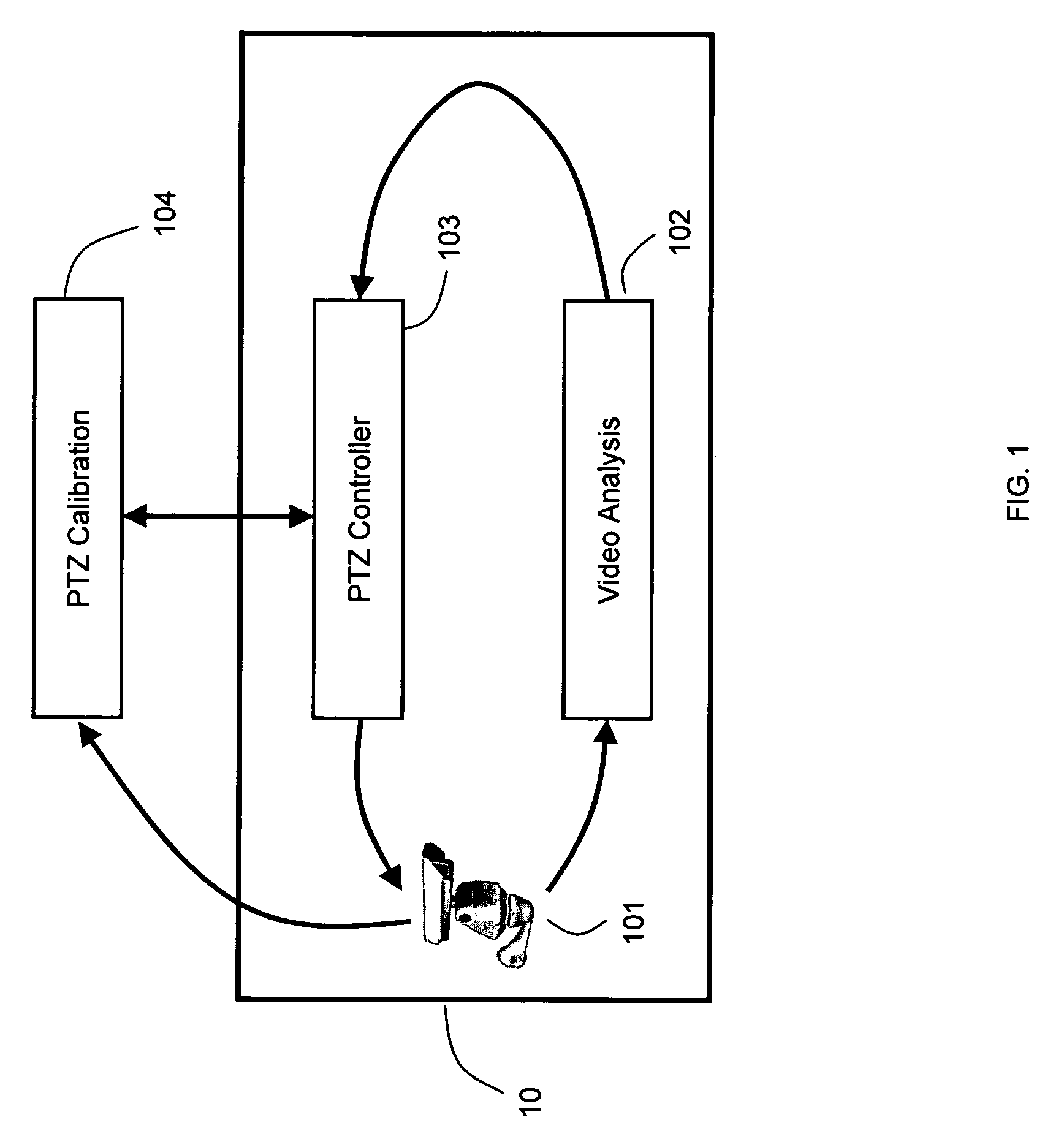
[0045]Embodiments of the invention may comprise part of an active camera system. A potential embodiment of an active camera system is depic...


PUM


Abstract

In one exemplary embodiment a method calibrates a pan-tilt-zoom (PTZ) camera system. The PTZ camera system may include a PTZ camera. The method may perform at least one of the following steps: determining a radial distortion of the PTZ camera; determining a base focal length of the PTZ camera; determining a zoom and magnification profile of the PTZ camera; determining an actuation delay of the PTZ camera system; determining a pan position mode speed and / or a tilt position mode speed of the PTZ camera; determining a pan velocity profile and / or a tilt velocity profile of the PTZ camera; determining a zoom position profile and / or a zoom duration profile of the PTZ camera; determining a query delay of the PTZ camera system; and determining a minimum query interval of the PTZ camera system.

Description

FIELD OF THE INVENTION[0001]The present invention is directed to a system and method for automatically acquiring the calibration parameters of a PTZ camera.BACKGROUND OF INVENTION[0002]Video-based security systems are commonly employed by businesses and other facilities, such as banks, stores and airports. Video-based security systems utilize a sensing device, such as a video camera, to obtain and record images within the video camera's field-of-view. The images recorded by the video camera may be monitored by a human operator, either in real-time or on a delay, and / or stored for future use.[0003]In an effort to keep costs down, many security systems are designed to utilize a small number of wide angle video cameras. However, while stationary camera systems provide a wide coverage area, they typically do not capture high resolution images.[0004]An alternative to the wide angle video camera system is an active camera system. An active camera system may utilize a small number of pan-t...

Claims


Application Information

Patent Timeline
Patent Type & Authority Patents(United States)
IPC IPC(8): H04N7/18H04N5/228H04N5/232G06K9/54H04N5/225G06K9/00
CPCG08B13/1963H04N17/002
Inventor GUPTA, HIMAANSHUCHOSAK, ANDREW J.TAYLOR, GEOFFREY R.BREWER, PAUL C.HAERING, NIELSLIPTON, ALAN J.
Owner MOTOROLA SOLUTIONS INC
Why Eureka
Try Eureka