
Pan, Tilt, Zoom Camera System for Cooling Electronics

a camera system and camera technology, applied in the field of pan, tilt, zoom camera system for cooling electronics, can solve the problems that the heat generated by the electronics of the board can still be significant enough to damage the ptz camera system or reduce its operational li

Active Publication Date: 2014-03-06
JOHNSON CONTROLS TYCO IP HLDG LLP
View PDF5 Cites 20 Cited by
  • Summary
  • Abstract
  • Description
  • Claims
  • Application Information

AI Technical Summary

Benefits of technology

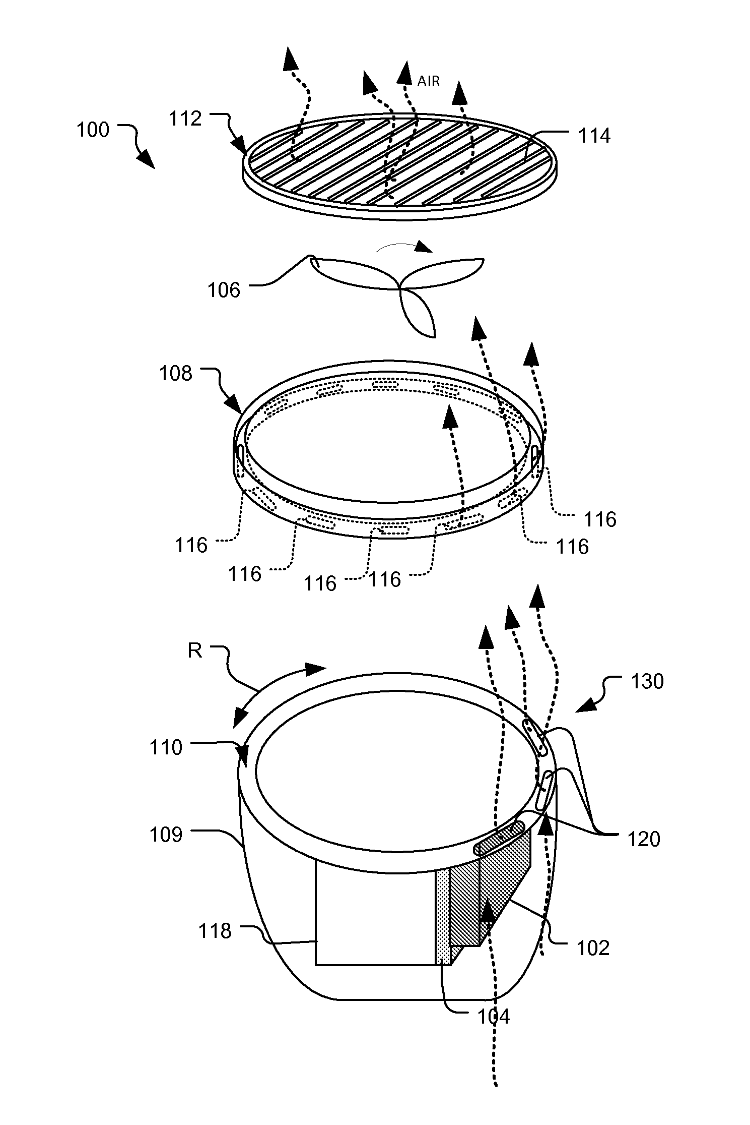
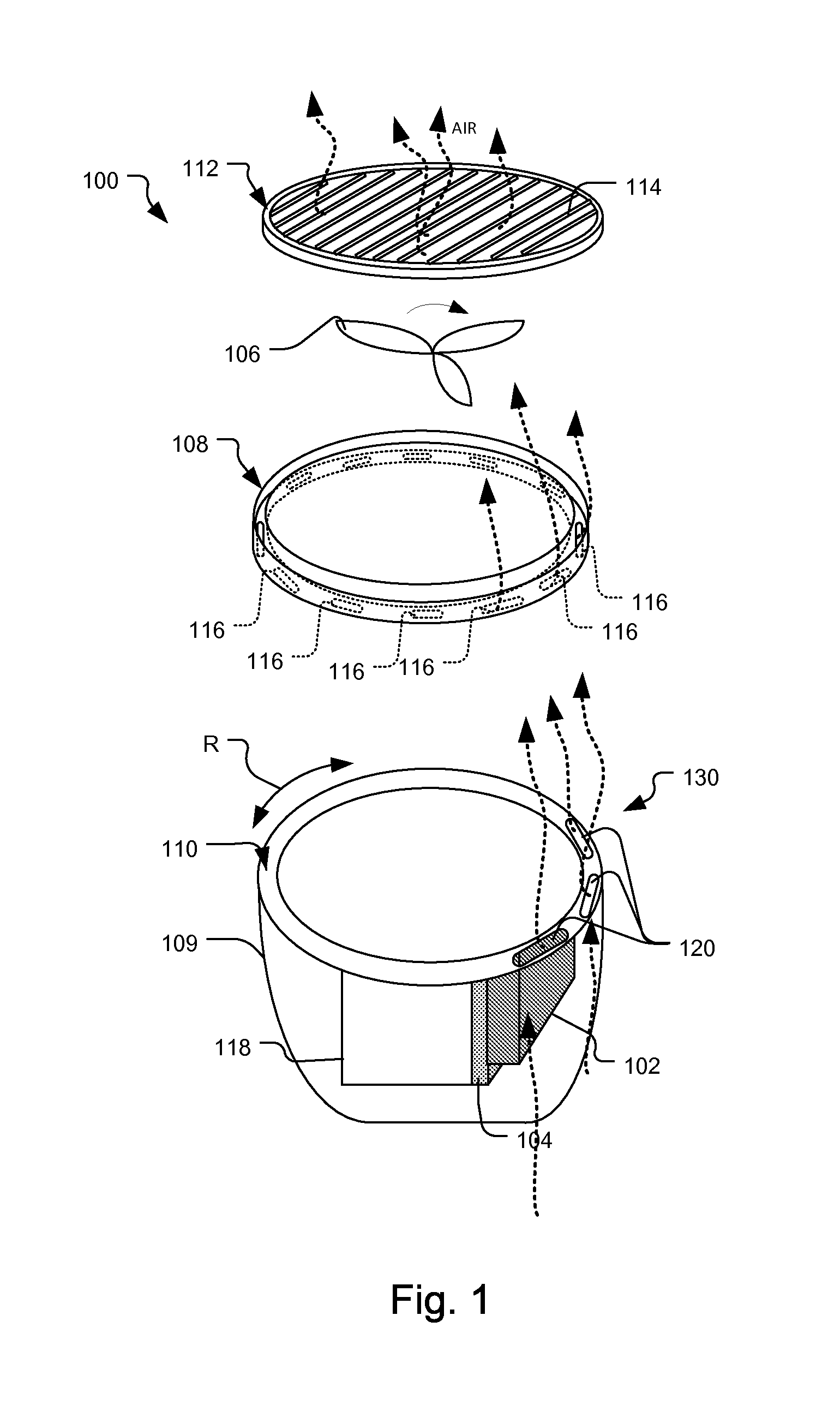
The present system is a cooling solution that uses air flow to prevent damage to critical elements such as electronics and cameras. It uses a disc valve system to direct air across these elements and dissipate heat. The technical effect of this system is to provide better cooling for various devices and to prevent damage caused by overheating.

Problems solved by technology

Although the electronics board is cooled by the heat sink and fan, heat generated by the electronics of the board can still be significant enough to damage the PTZ camera system or reduce its operational lifetime.

Method used


Image

  • Pan, Tilt, Zoom Camera System for Cooling Electronics
  • Pan, Tilt, Zoom Camera System for Cooling Electronics
  • Pan, Tilt, Zoom Camera System for Cooling Electronics

Examples


Embodiment Construction

[0022]The invention now will be described more fully hereinafter with reference to the accompanying drawings, in which illustrative embodiments of the invention are shown. This invention may, however, be embodied in many different forms and should not be construed as limited to the embodiments set forth herein; rather, these embodiments are provided so that this disclosure will be thorough and complete, and will fully convey the scope of the invention to those skilled in the art.

[0023]As used herein, the term “and / or” includes any and all combinations of one or more of the associated listed items. Further, the singular forms of the articles “a”, “an” and “the” are intended to include the plural forms as well, unless expressly stated otherwise. It will be further understood that the terms: includes, comprises, including and / or comprising, when used in this specification, specify the presence of stated features, integers, steps, operations, elements, and / or components, but do not prec...


PUM


Abstract

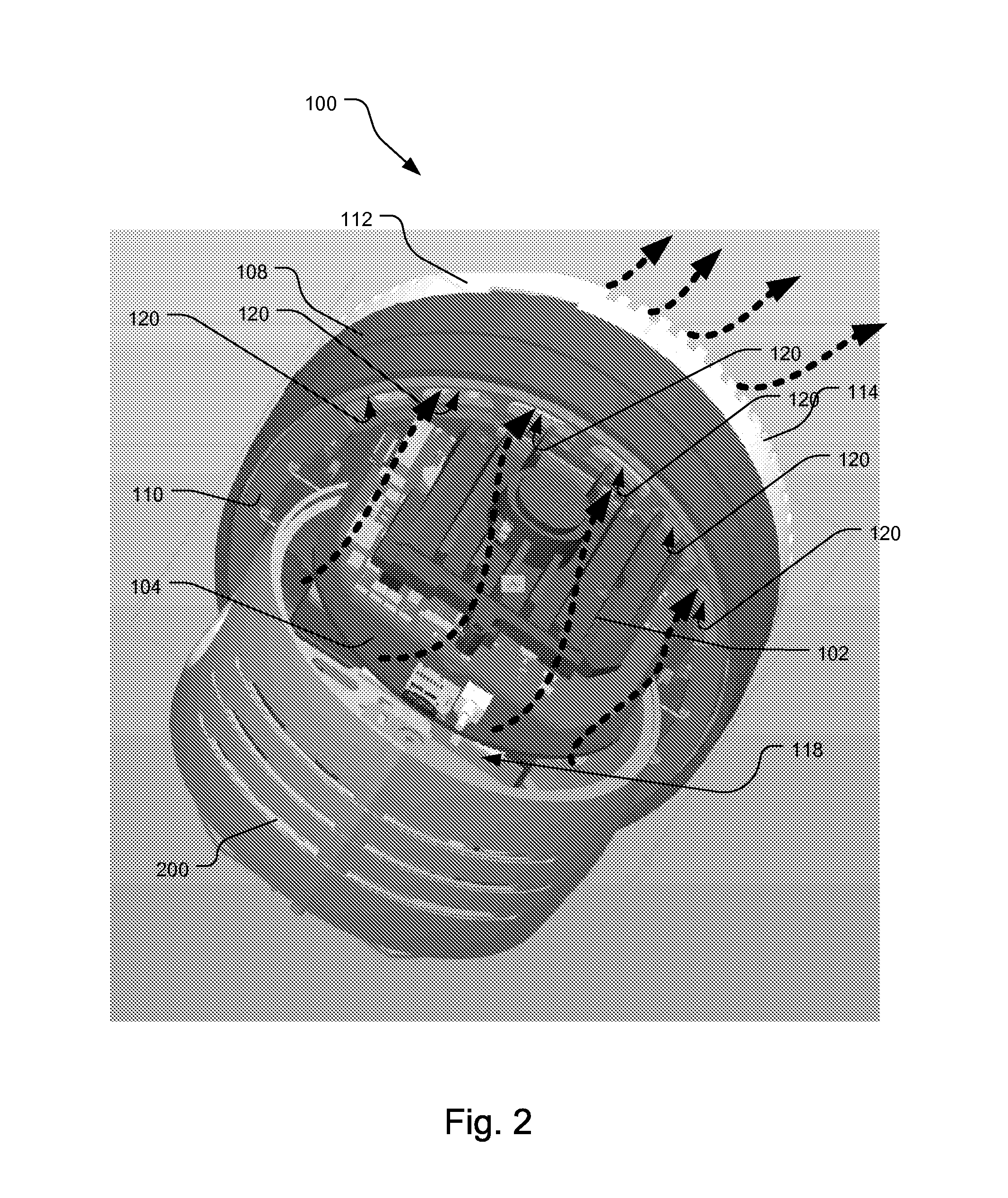
A pan tilt zoom (PTZ) camera system implements a disc valve system to enhance the cooling of electronics. The disc valve system includes a static camera base and a rotating camera pan bearing. The static camera base has static base vent slots arranged along the perimeter of the static camera base. The rotating camera pan bearing includes at least one pan bearing vent slot that aligns with the static base vent slots. During rotation of the rotating camera pan bearing, the at least one pan bearing vent slot aligns with the static base vent slots enabling movement of air over electronics of the (PTZ) camera system.

Description

RELATED APPLICATIONS[0001]This application claims the benefit under 35 U.S.C. §119(e) of U.S. Provisional Application No. 61 / 697,709, filed on Sep. 6, 2012, which is incorporated herein by reference in its entirety.BACKGROUND OF THE INVENTION[0002]Video surveillance cameras are often used for monitoring areas inside or outside buildings. Examples of monitored areas include parking lots, casinos, hospitals, or government buildings. These video surveillance cameras capture video images and other data from the monitored areas and typically send those video images to a control system and / or network video recorder (NVR).[0003]One type of video surveillance camera is a pan, tilt, zoom (PTZ) camera system. A PTZ camera system rotates or pans a camera about a vertical axis and also changes the direction of or tilts the camera to capture different scenes within the monitored areas. Some PTZ camera systems are programmed to automatically pan and tilt the cameras based on pre-set viewing selec...

Claims


Application Information

Patent Timeline
Patent Type & Authority Applications(United States)
IPC IPC(8): G03B17/55
CPCG03B17/55H04N23/51
Inventor MCBRIDE, FREDERICK MICHAELMCKEE, DAVID
Owner JOHNSON CONTROLS TYCO IP HLDG LLP
Learn More