Eureka AIR delivers breakthrough ideas for toughest innovation challenges, trusted by R&D personnel around the world.

Display instrument

Inactive Publication Date: 2005-02-15
CONTINENTAL AUTOMOTIVE GMBH
View PDF19 Cites 28 Cited by
  • Summary
  • Abstract
  • Description
  • Claims
  • Application Information

AI Technical Summary

Benefits of technology

The invention is therefore based on the object of significantly improving the supply of light for two illuminated pointers which are arranged one on top of the other. In particular, the intention is to ensure that the design and assembly are as simple as possible and that as little scattered light as possible occurs.
This permits a very simple design which can be simplified even further if the drive shaft of a pointer serves as a light guide and part of the drive shaft is embodied as a light splitter. In this arrangement, there is virtually no need for any additional parts because with this solution an already existing part, namely the drive shaft, assumes a further function.

Problems solved by technology

The effort incurred, in particular to supply the illuminated pointers with light is, however, considerable.
The design becomes particularly difficult if the display instrument has two illuminated pointers which are arranged one on top of the other and have a common axis of rotation.
The previously known arrangements are relatively complicated and also have the disadvantage that scattered light which illuminates the dial occurs so that the contrast between the illuminated pointers and the dial background is reduced.

Method used


Image

  • Display instrument
  • Display instrument

Examples


Embodiment Construction

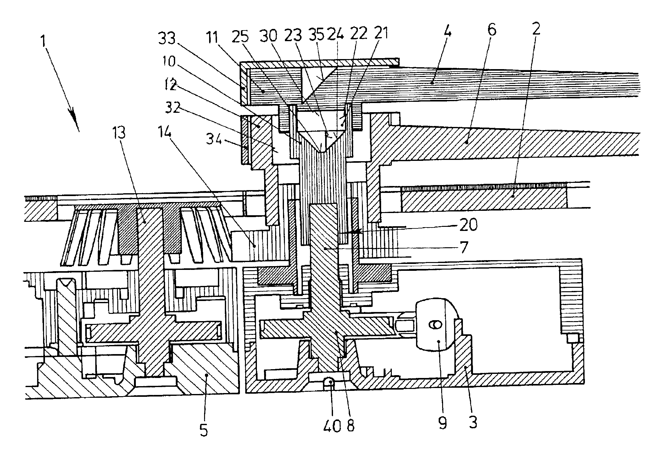
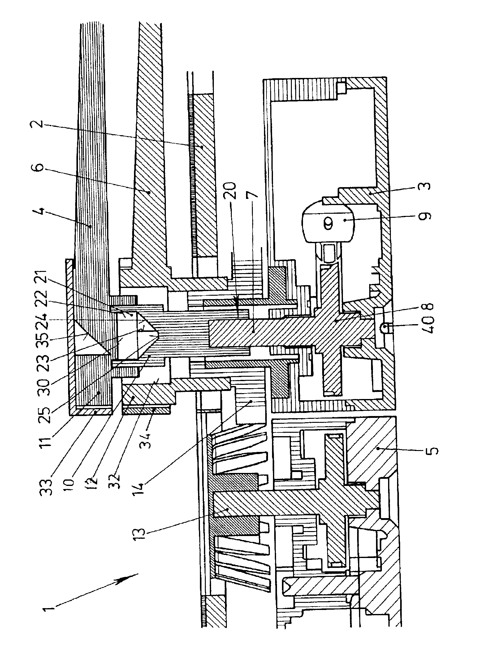
The FIGURE shows a cross section through a display instrument 1. Below the dial 2 there is a first drive unit 3 for an upper illuminated pointer 4 and a second drive unit 5 for a lower illuminated pointer 6 which is arranged underneath the upper illuminated pointer 4.

The first drive unit 3 is coupled to the upper illuminated pointer 4 via a drive shaft 7 which is constructed as a light guide. The drive shaft 7 is composed of a main part 8, which is connected to an electrical actuating motor 9 by means of a worm gear mechanism. The light splitter 10 is plugged onto the main part 8 of the drive shaft 7 and thus functions as an extension of the main part 8 of the drive shaft 7. The upper illuminated pointer 4 is plugged, with its head 11, onto the upper end of the light splitter 10.

The head 12 of the lower illuminated pointer 6 is constructed as a ring which is located coaxially with respect to the light splitter 10. It is driven via a worm gear mechanism 14 by the drive shaft 13 of th...


PUM


Abstract

A display instrument with two illuminated pointers, in which instrument the illuminated pointers (4, 6) are supplied with light via a light splitter (10). The latter has a frustum-shaped depression (21) so that a portion of the light is radiated in the axial direction and passes into the upper illuminated pointer (4). A further portion is scattered radially at the generated surface (24) of the frustum (23) and passes into the lower illuminated pointer (6).

Description

FIELD AND BACKGROUND OF THE INVENTIONThe invention relates to a display instrument having at least two illuminated pointers which are located one on top of the other, are each composed of a head and a pointer lug and can be rotated independently of one another about a common display axis, the illuminated pointers being composed of a light-guiding material and each having a light entry face, and the light injected there exiting on the side of the pointer lugs facing the viewer.Such display instruments have become established in particular in the construction of vehicles because they ensure reliable readability in the dark: the illuminated pointer lugs form, for the driver, a clear contrast against a dark dial with numerals which are also illuminated.The effort incurred, in particular to supply the illuminated pointers with light is, however, considerable. Light guides are used to guide light from a light source in the housing of the display instrument to the light entry face of the i...

Claims


Application Information

Patent Timeline
IPC IPC(8): G01D13/22G01D13/00G01D11/28G01P1/08B60K35/00G01D13/28G12B11/00
CPCG01D11/28G01D13/22B60K37/02Y10S116/05Y10S116/36B60K35/60B60K2360/336B60K2360/698
Inventor BREINICH, HERBERTESCHENBACH, BERTRAMMITTENBUHLER, KARL-HEINZVORBERG, SABINE
Owner CONTINENTAL AUTOMOTIVE GMBH
Why Eureka
Eureka Blog
Learn More