
Display method and apparatus for navigation system

a navigation system and display method technology, applied in surveying and navigation, navigation instruments, instruments, etc., can solve the problems of inability to easily identify icons, difficulty in specifying destinations, and navigation system not performing the route guidance function, etc., to achieve accurate and enlarged view of positional relationships, easy identification of pois, and easy to identify the

Inactive Publication Date: 2005-02-15
ALPINE ELECTRONICS INC
View PDF4 Cites 86 Cited by
  • Summary
  • Abstract
  • Description
  • Claims
  • Application Information

AI Technical Summary

Benefits of technology

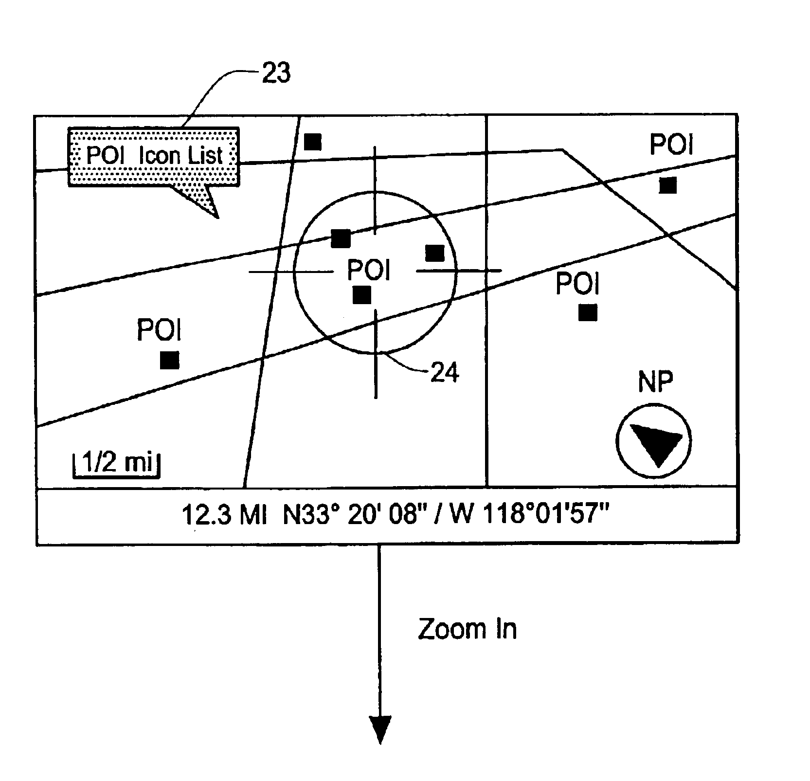
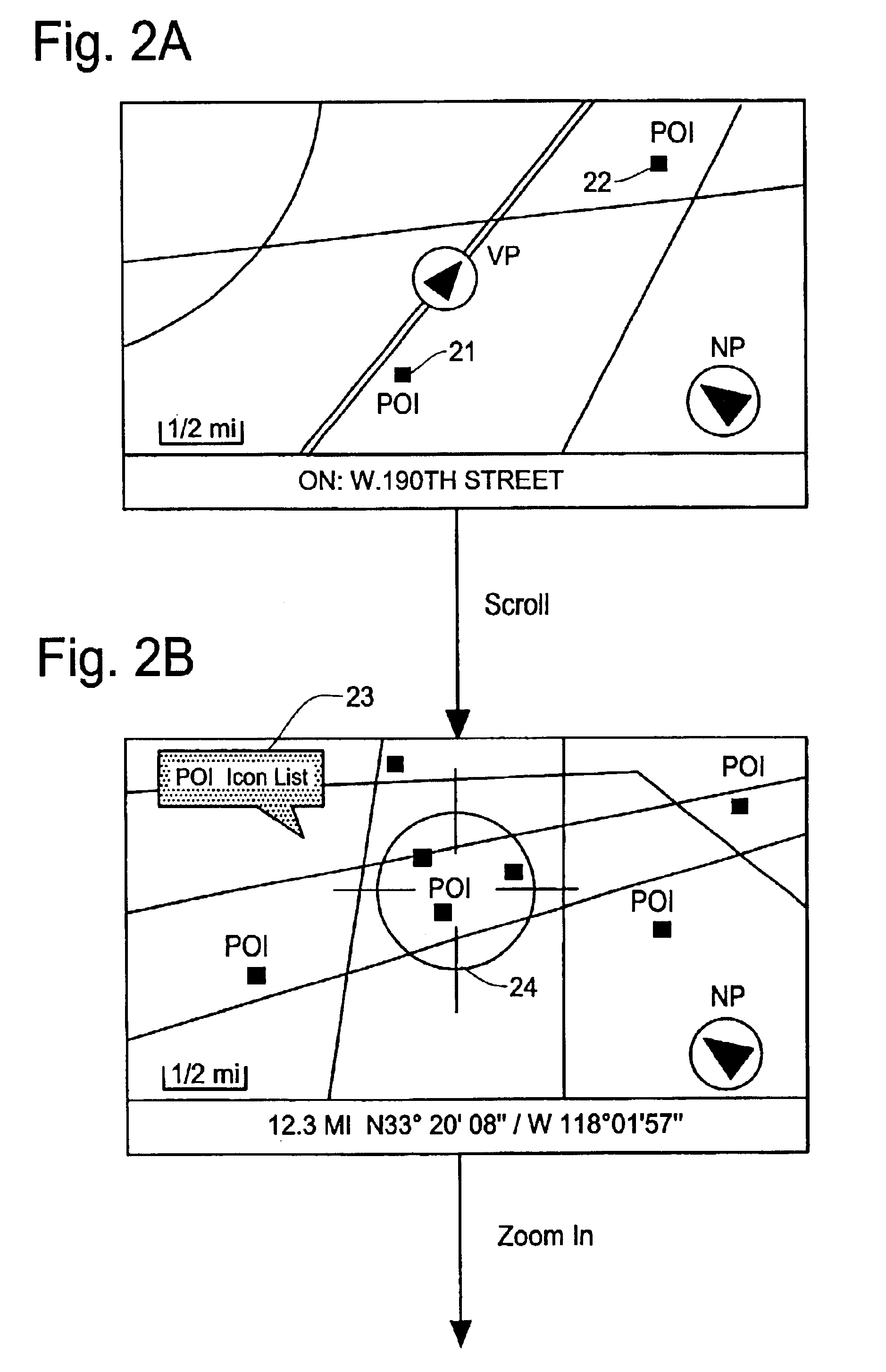
It is, therefore, an object of the present invention to provide a navigation system which enables a user to more easily identify “Point of Interest (POI)” icons within a specified small area, such as a cursor circle when the POI icons are crowded within such an area.
The display method and apparatus of the present invention is capable of more clearly displaying POI icons by: shifting the POI icons in radial directions in such a way that the user can easily see the relationship between the original positions and the shifted POI icons.
In another aspect of the display method of the present invention, rather than displacing the POI icons to the position rims, the navigation system shifts the POI icons in the radial direction in proportion to the distance of the original POI icons from the center. Thus, the displaced POI icons establish an accurate and enlarged view of the positional relationship among the original POI icons. The position rims function as position scales to assist the user to know the positional differences in the POI icons. The displaced POI icons are connected to the original position marks through the lead lines, thereby distinguishing the displaced POI icons from other POI icons.
A further aspect of the present invention is a display apparatus for a navigation system. The display apparatus is constituted by various means for achieving the POI search method described above which shifts the POI icons in the radial directions. The POI icons are shifted to be located on the position rim and connected to the original position marks by the lead lines. Alternatively, the POI icons are shifted in proportion to the distances from the center, thereby establishing an enlarged view of the positional relationship of the POI icons.
According to the present invention, the navigation system enables the user to easily identify the POIs in a cursor circle, even if the POIs are crowded in a small area, by automatically moving them to position rims and showing position marks of the POIs to indicate the accurate positions in the cursor circle. Thus the user can easily check the POI icons and select one of the POIs as his destination.

Problems solved by technology

However, in this, situation, the navigation system does not perform the route guidance function because the destination is not specified.
However, the user may have difficulty in specifying the destination when searching the POI icons on the map image because sometimes too many POIs are located in a small area such as in a downtown, a shopping mall or other large compounds.
In such a situation, although the user scrolls and moves the crowded POI icons around the center in the map images, he cannot easily identify the icons because some POI icons.
The problem becomes worse if there are many overlapping POI icons (for example, restaurants) crowded in such an area.
Further, because a monitor screen of a navigation system has a limited resolution, it is difficult to display POI icons with a small size while maintaining clear view for the user.
As described in the foregoing, it is not always possible to display POI icons and their positions on the map image due to the limitation of the screen resolution and POI icon sizes.
As a result, it is not possible to decide as to which side of the street a particular POI is located.
Thus, it is not easy for the user to specify the destination by the method of directly using POI icons on the map image.

Method used


Image

  • Display method and apparatus for navigation system
  • Display method and apparatus for navigation system
  • Display method and apparatus for navigation system

Examples


Embodiment Construction

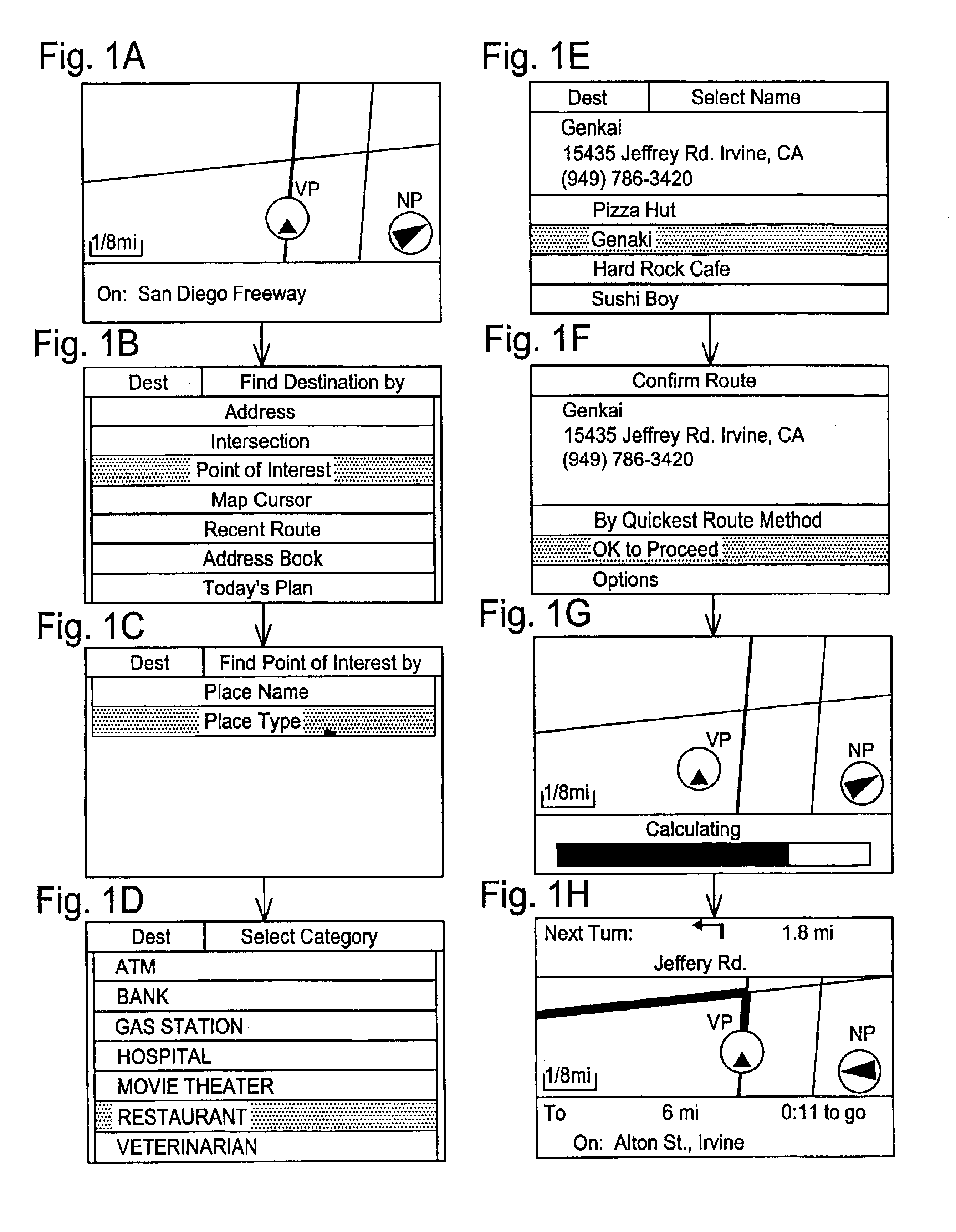
The present invention is described in detail with reference to the accompanying drawings. The navigation system of the present invention is designed to enable a user to easily see an accurate position of points of interest (POIs) by their icons (POI icons) on a map image. In particular, the display method of the present invention is useful when many POI icons are located in a small area. The navigation system displaces the POI icons within a region of attention in radial directions to a position rim or to positions in proportion to the original POI positions relative to a center. Typically, such a region of attention is defined by a cursor of a navigation screen, however any predefined region mark can be used. Preferably, a size of such a region mark can be adjustable by a user.

Such a displacement operation is initiated either automatically or by an instruction from the user. Thus, by changing a position or a size of the region mark on the map image, the navigation system starts dis...


PUM


Abstract

A display method and apparatus for navigation system enables a user to easily see crowded POI icons and their positions in a small area on the map image by shifting the positions of POI icons in radial directions. The display method includes the steps of specifying POI icons on a map image within a region of a predefined region mark, forming a position rim which is a circle with a center of the region mark, displacing the POI icons within the region mark in radial directions to the position rim, displaying position marks at positions where the POI icons are located before the displacement within the region mark, and displaying lead lines each connecting the POI icon displaced to the position rim and the corresponding position mark.

Description

FIELD OF THE INVENTIONThis invention relates to a display method and apparatus for navigation system for displaying “Point of Interest (POI)” icons on a map image, and more particularly, to a display method and apparatus which is capable of more clearly displaying the POI icons and their positions in a region of attention by displacing the POI icons in radial directions relative to a reference center.BACKGROUND OF THE INVENTIONA navigation system performs travel guidance for enabling a user to easily and quickly reach the selected destination. A typical example is a vehicle navigation system where a user drives a car having a vehicle navigation system. Such a navigation system detects the position of the user or user's vehicle, reads out map data pertaining to an, area at the current vehicle position from a data storage medium, for example, a CD-ROM (compact disc read-only memory), a DVD (digital versatile disc), or a hard disc. Alternatively, such map data can be provided to the us...

Claims


Application Information

Patent Timeline
IPC IPC(8): G01C21/34G01C21/36
CPCG01C21/3682
Inventor HAN, MAUNG W.
Owner ALPINE ELECTRONICS INC
Learn More