Strapping machine with strap path access guide

a strapping machine and access guide technology, applied in the field of strapping machines, can solve the problems of strap damage and limited access area

Inactive Publication Date: 2005-02-22
SIGNODE IND GRP
View PDF7 Cites 31 Cited by
  • Summary
  • Abstract
  • Description
  • Claims
  • Application Information

AI Technical Summary

Benefits of technology

The benefits and advantages of the present invention will become more readily apparent to those of ordinary...

Problems solved by technology

As such, the area available for accessing the strap is limited, and there exists the...

Method used


Image

  • Strapping machine with strap path access guide
  • Strapping machine with strap path access guide
  • Strapping machine with strap path access guide

Examples


Embodiment Construction

While the present invention is susceptible of embodiment in various forms, there is shown in the drawings and will hereinafter be described a presently preferred embodiment with the understanding that the present disclosure is to be considered an exemplification of the invention and is not intended to limit the invention to the specific embodiment illustrated.

It should be further understood that the title of this section of this specification, namely, “Detailed Description Of The Invention”, relates to a requirement of the United States Patent Office, and does not imply, nor should be inferred to limit the subject matter disclosed herein.

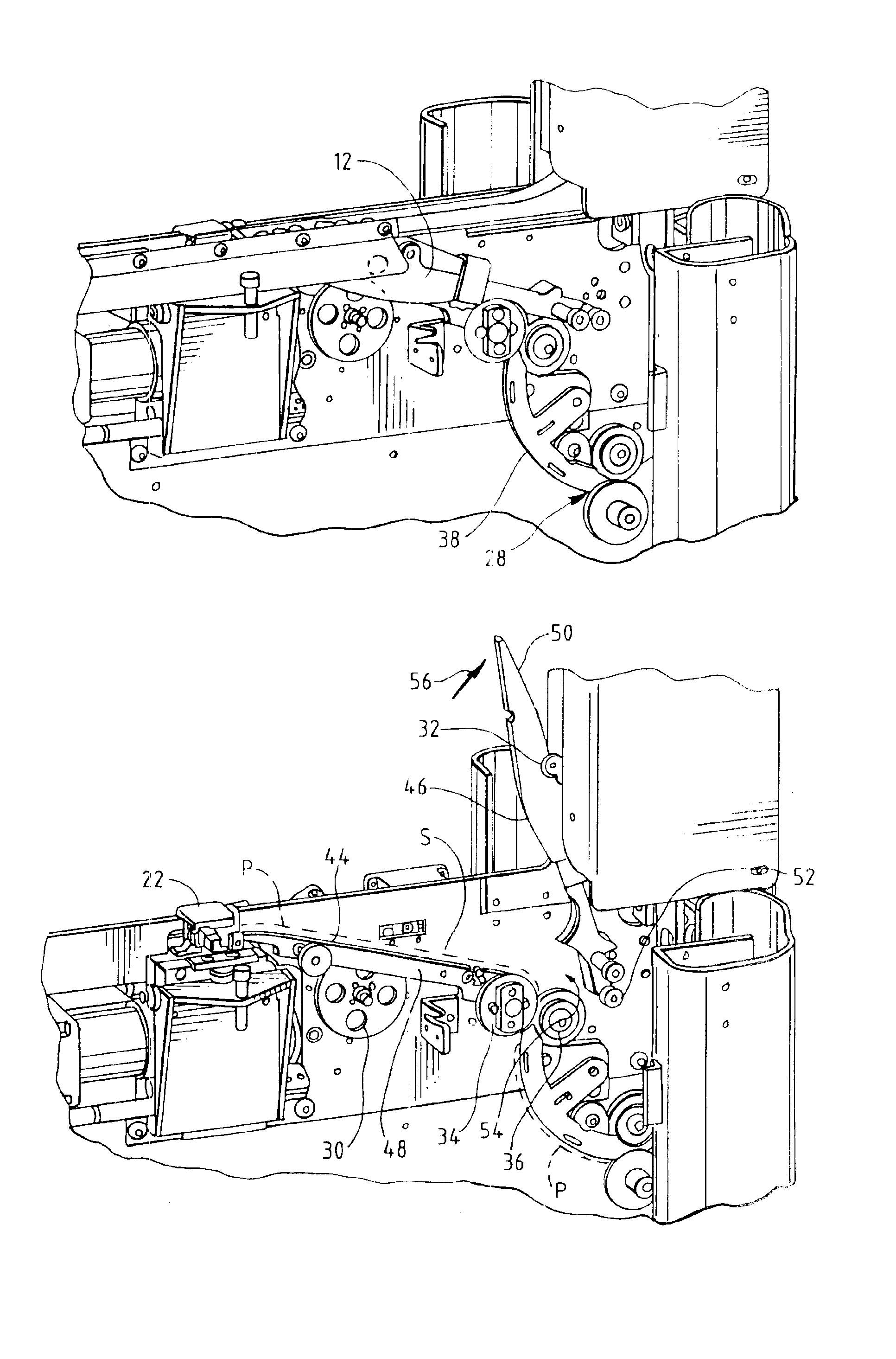
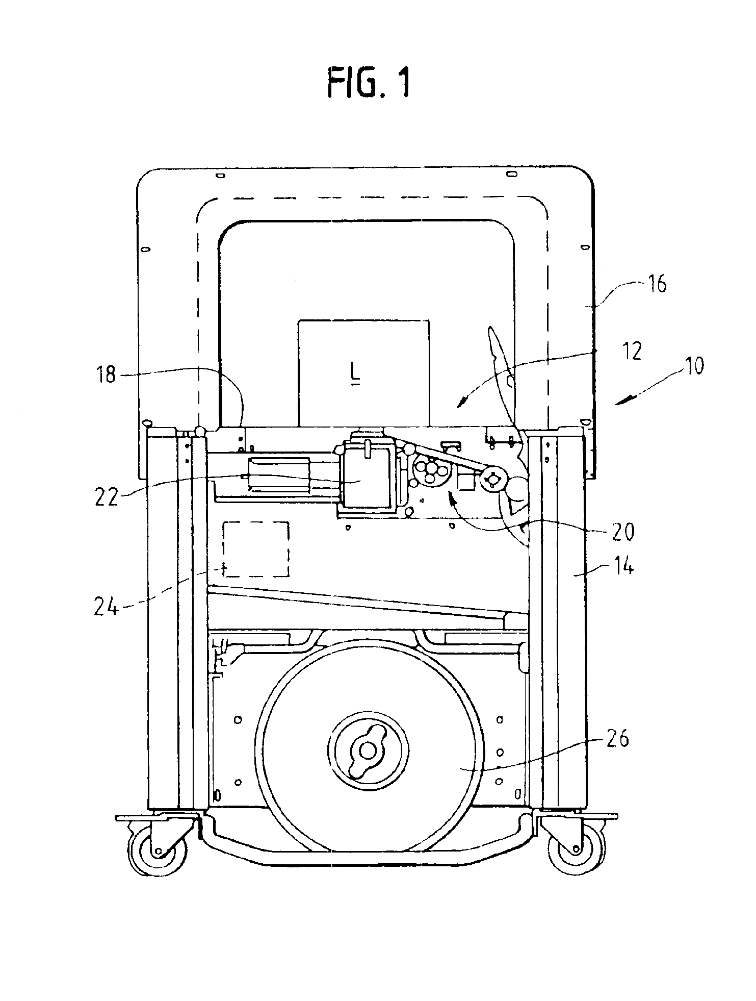
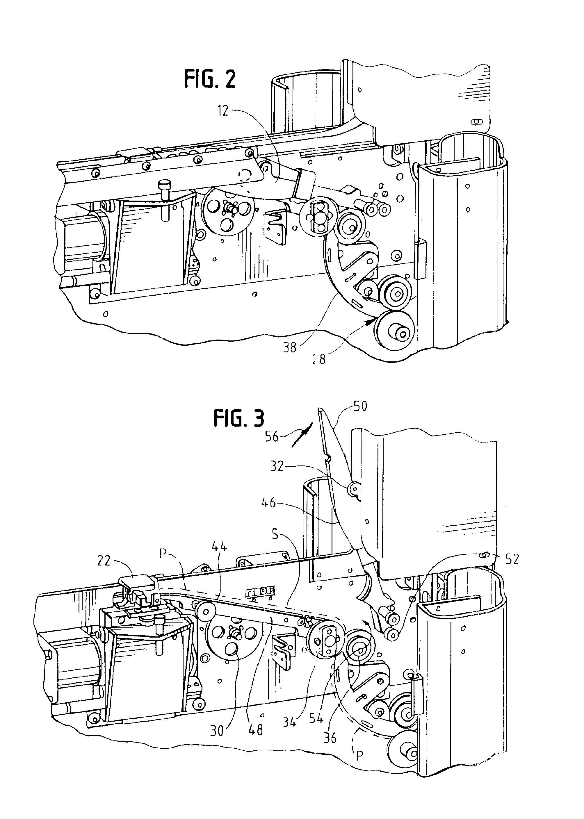
Referring to the figures and in particular FIG. 1, there is shown a strapping machine 10 having a strap path access guide 12 embodying the principles of the present invention. The strapping machine 10 includes, generally, a frame 14, a strap chute 16 and a table top or work surface 18. A feed assembly 20 and a strapping head 22 are mounted below the...


PUM


Abstract

A strap path access guide is configured for use in a strapping machine of the type having a feed assembly a chute and a strapping head disposed between the feed assembly and the chute. The strapping machine is configured to receive first and second courses of associated strap material, position, tension and seal the strap material around a load. The strap path access guide is disposed along the feed assembly between a pair of tensioning wheels and the strapping head. The strap path access guide includes a fixed lower guide portion extending between the tensioning wheels and the strapping head. The fixed lower guide portion defines a lower surface of the strap path. A pivotable upper guide portion is pivotable about a pivot that is spaced from and rearwardly beyond the tensioning wheels. The upper guide portion is pivotable between a closed position in which the upper and lower guide portions cooperate with one another to define the strap path and an open position in which the strap path is fully accessible. The upper guide portion is pivotable in a plane transverse to a direction of travel of strap material through the strap path. A latching element secures the upper guide portion in the closed position.

Description

BACKGROUND OF THE INVENTIONThe present invention is directed to an improvement in a strapping machine. More particularly, the present invention is directed to a strapping machine having a readily accessible strap path.Strapping machines are in widespread use for securing straps around loads. One type of known strapper is a stationary unit that includes a strapping head or weld head and drive mechanism mounted within a frame. A chute is mounted to the frame, through which the strapping material is fed. In a typical arrangement, a table-top or work surface is likewise mounted to the frame.In a typical stationary strapper, the chute is mounted from about the work surface, and the strapping head is mounted below the work surface. Strap is fed from a source or dispenser to the strapping or welding head. The strapping head provides a number of functions. First, it includes a plurality of grippers for gripping portions of the strap during the course of a strapping operation. The strapping ...

Claims


Application Information

Patent Timeline
IPC IPC(8): B65B13/06B65B13/18B65B13/00
CPCB65B13/06B65B59/04B65B13/185B65B13/18
Inventor HABERSTROH, JAMES A.PEARSON, TIMOTHY B.
Owner SIGNODE IND GRP
Why Eureka
Try Eureka