Dump truck with payload weight measuring system and method of using same

Inactive Publication Date: 2005-02-22
CATERPILLAR INC
View PDF14 Cites 50 Cited by
  • Summary
  • Abstract
  • Description
  • Claims
  • Application Information

AI Technical Summary

Problems solved by technology

While strut pressures provide a fairly good representation of the truck's weight, other factors such as strut seal friction and strut rod bending can re

Method used


Image

  • Dump truck with payload weight measuring system and method of using same
  • Dump truck with payload weight measuring system and method of using same
  • Dump truck with payload weight measuring system and method of using same

Examples


Embodiment Construction

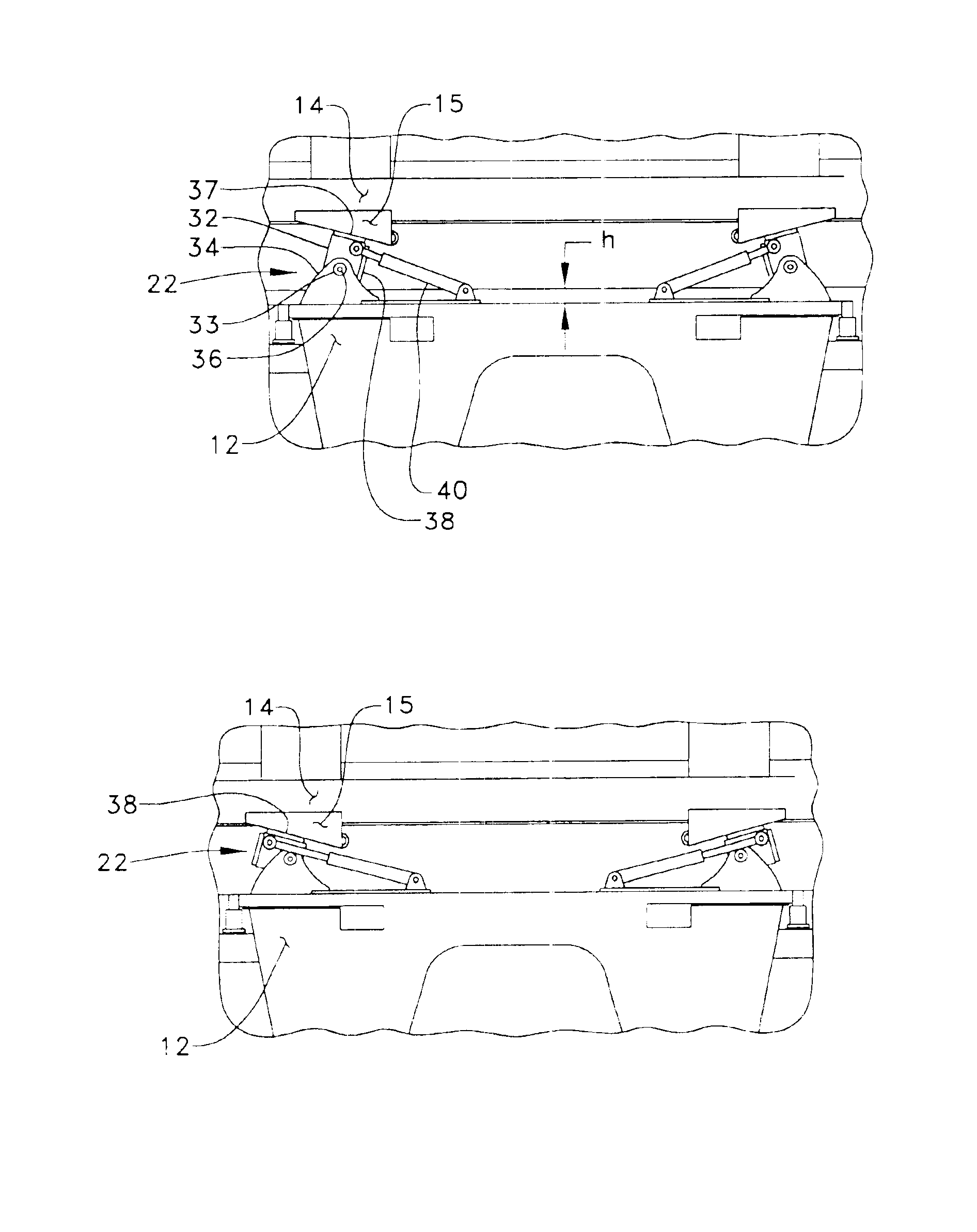
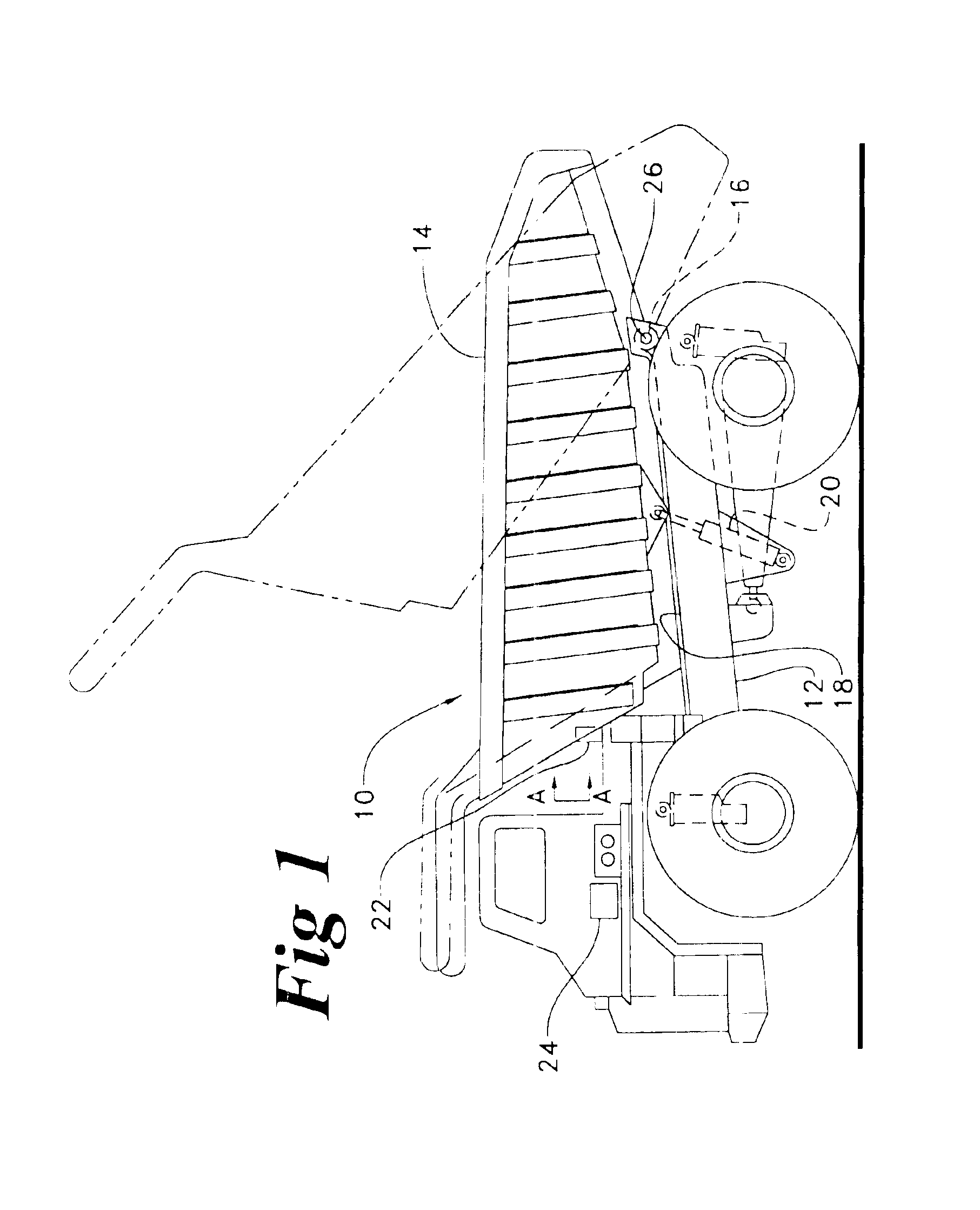
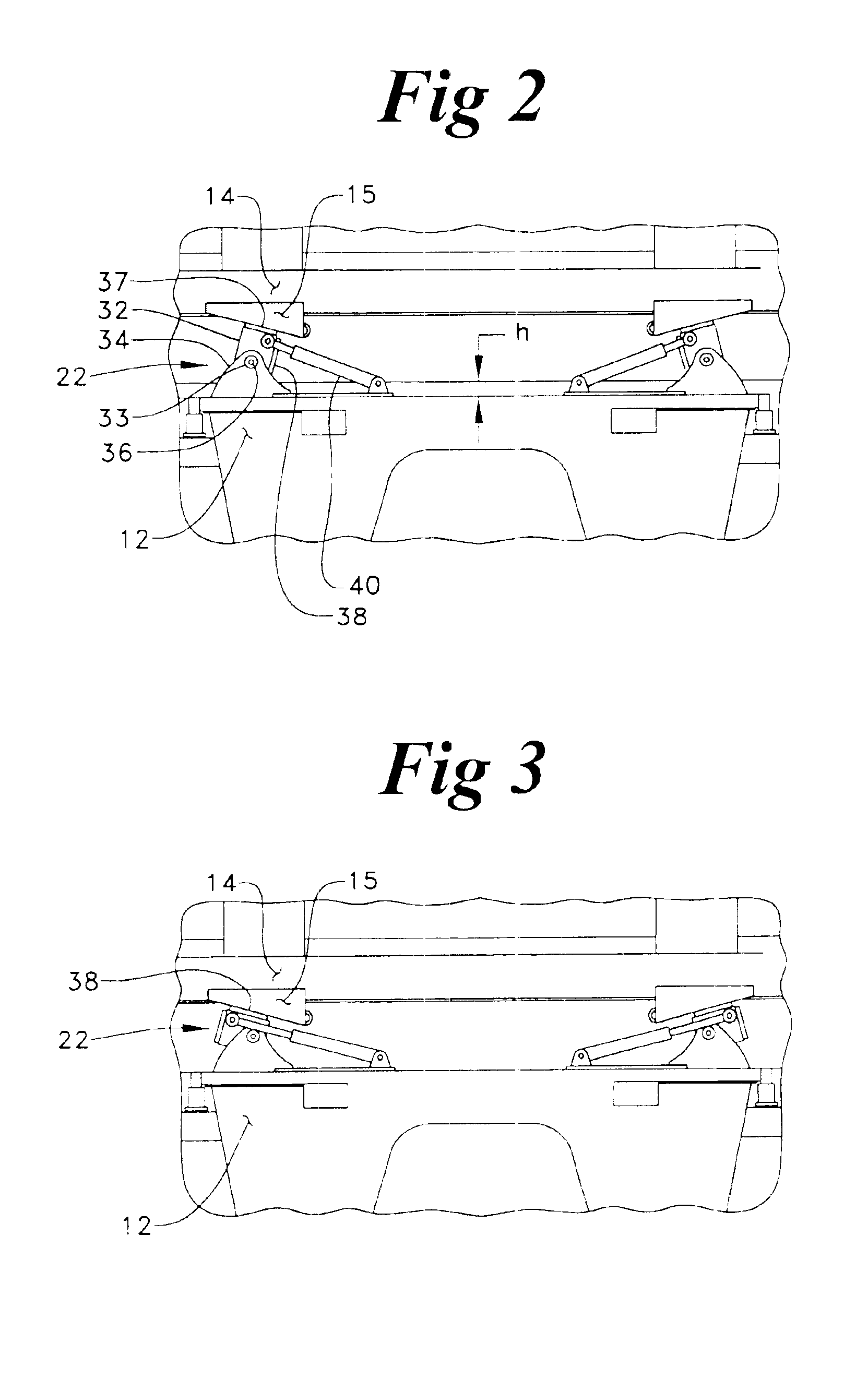
Referring now to FIG. 1, a dump truck 10 includes a dump body 14 pivotably attached to a chassis 12. Although dump truck 10 is illustrated as an off highway truck, those skilled in the art will appreciate that the present invention is applicable to virtually all dump trucks. Dump body 14 pivots about a pair of pivot pins 16 when moving from its travel position, as shown, toward its dump position as shown in shadow. This movement of dump body 14 is controlled by at least one dumping actuator 20 in a conventional manner. Each of the pivot pins 16 include at least one payload weight sensor 26, which is preferably a strain gauge appropriately positioned within the pivot pin. Nevertheless, those skilled in the art will appreciate that other types of weight sensors could be substituted, such as a load cell, without departing from the present invention. When dump body 14 is in its travel position as shown in FIG. 1, the weight of dump body 14, and hence its contents, are supported primaril...


PUM


Abstract

Accurately measuring the payload weight of dump trucks, especially off highway trucks, is important to efficient operation of most applications, such as in the mining industry. An under-loaded truck decreases efficiency in a known manner. In addition, over-loading a truck can decrease efficiency in the long run by such things as shortening truck component life due to excessive wear, such as on the drive train. The present invention seeks a more accurate payload measurement by positioning the dump body between its travel position and its dumping position. In the payload measuring position, the dump body is supported at four points, which are preferably pins equipped with shear strain gauges. After measuring the payload weight, the dump body is returned to its travel position for transport.

Description

TECHNICAL FIELDThe present invention relates generally to measuring the payload weight in a dump truck, and more particularly to measuring a dump truck payload weight when the dump body is between its travel position and its dumping position.BACKGROUNDMany existing off highway truck payload measurement systems calculate payload weight by measuring the truck's four suspension strut pressures, and use a combination of formulas and empirical data to calculate the payload weight. For instance, co-owned U.S. Pat. No. 5,182,712 to Kyrtsos et al. teaches a dynamic payload monitor with the capability of measuring the compression condition of the truck's four struts while the truck is in motion, in order to produce an even more accurate measurement than that likely possible when the truck is in a stationary position. These strut pressure strategies can typically produce payload weight accuracies on the order of plus or minus 3-5%. While strut pressures provide a fairly good representation of...

Claims


Application Information

Patent Timeline
IPC IPC(8): G01G19/08G01G19/12
CPCG01G19/12
Inventor BENDER, JOHN L.
Owner CATERPILLAR INC
Why Eureka
Try Eureka