Diagnostic blown fuse indicator

a technology of fuse indicator and fuse, applied in the field of fuse, can solve the problems of insufficient heat generation of small current that runs through the conductive layer, typical blowing of fuse, and inability to distinguish between short circuit failure or overcurrent situation,

Inactive Publication Date: 2005-02-22
LITTELFUSE INC
View PDF34 Cites 44 Cited by
  • Summary
  • Abstract
  • Description
  • Claims
  • Application Information

AI Technical Summary

Benefits of technology

An advantage of the present invention is to provide a blown fuse indicator having diagnostic capabilities, such that the indicator provides a perceivable distinction between a blown fuse due to an overload and a blown fuse due to a short circuit.
Another advantage of the present invention is to provide a diagnostic blown fuse indicator that is adaptable for use with many existing blown fuse indication technologies.
Additional features and advantages of the present invention will be described in and apparent from the Detailed Description of the Preferred Embodiments and the Drawings.

Problems solved by technology

When a short circuit occurs, the fuse typically blows at this high resistance area.
In normal operation, most of the current runs through the fuse element, and the small amount of current that runs through the conductive layer does not produce enough heat to raise the temperature of the responsive layer above its transition temperature.
None of the indicators, however, differentiate between a short circuit failure or an overcurrent situation.
The known indicators do not provide such a tool.

Method used


Image

  • Diagnostic blown fuse indicator
  • Diagnostic blown fuse indicator
  • Diagnostic blown fuse indicator

Examples


Embodiment Construction

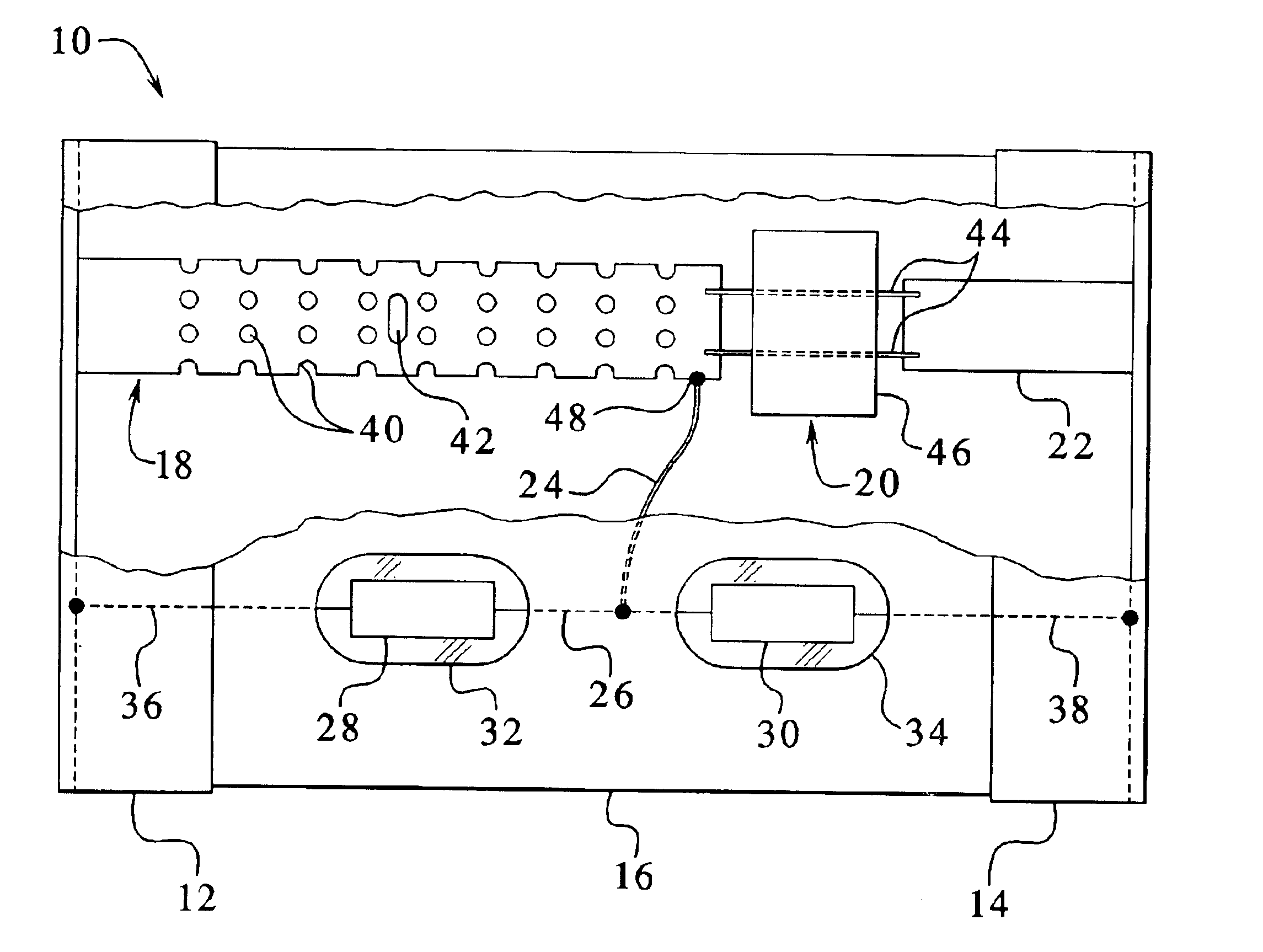
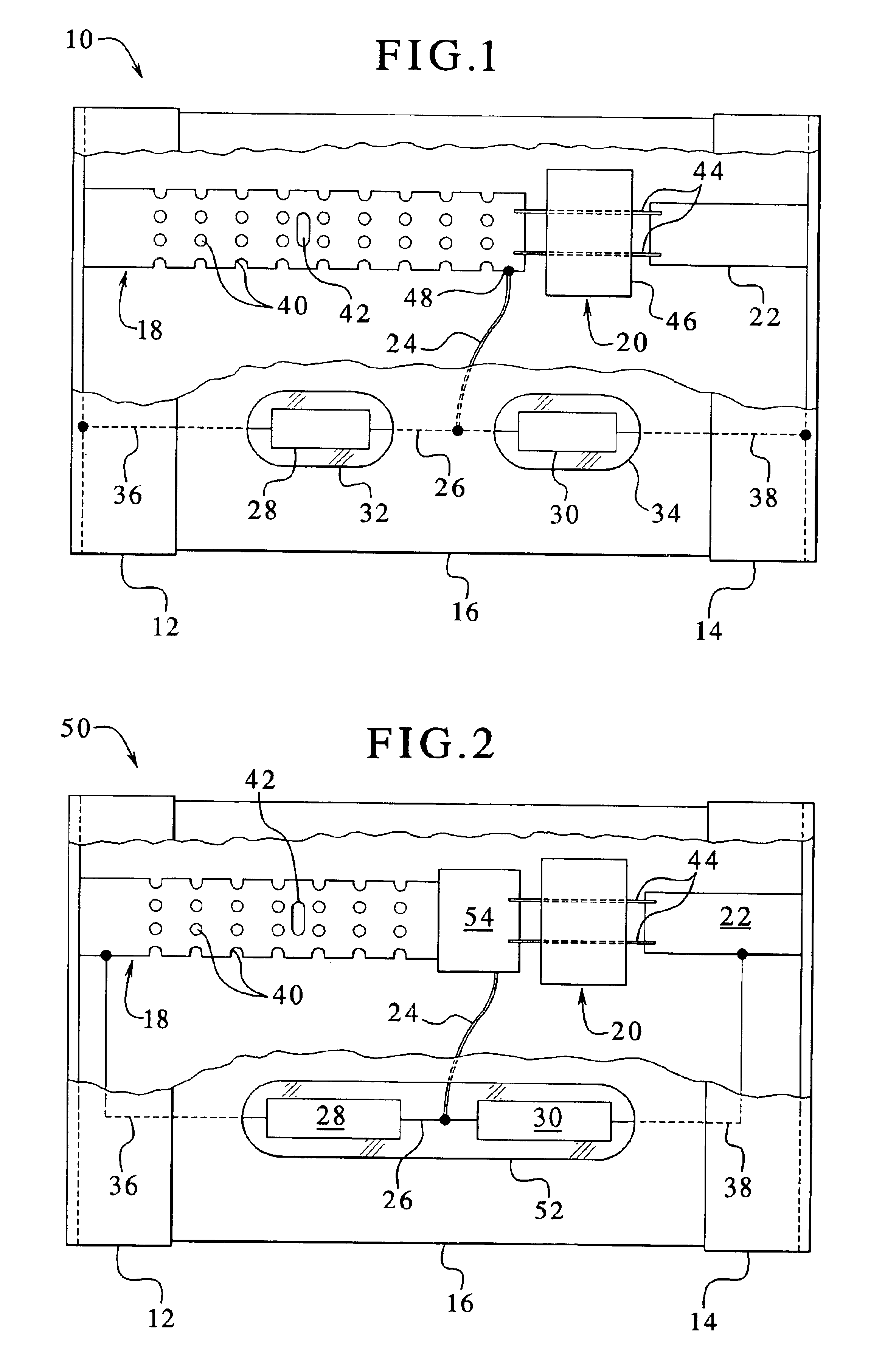
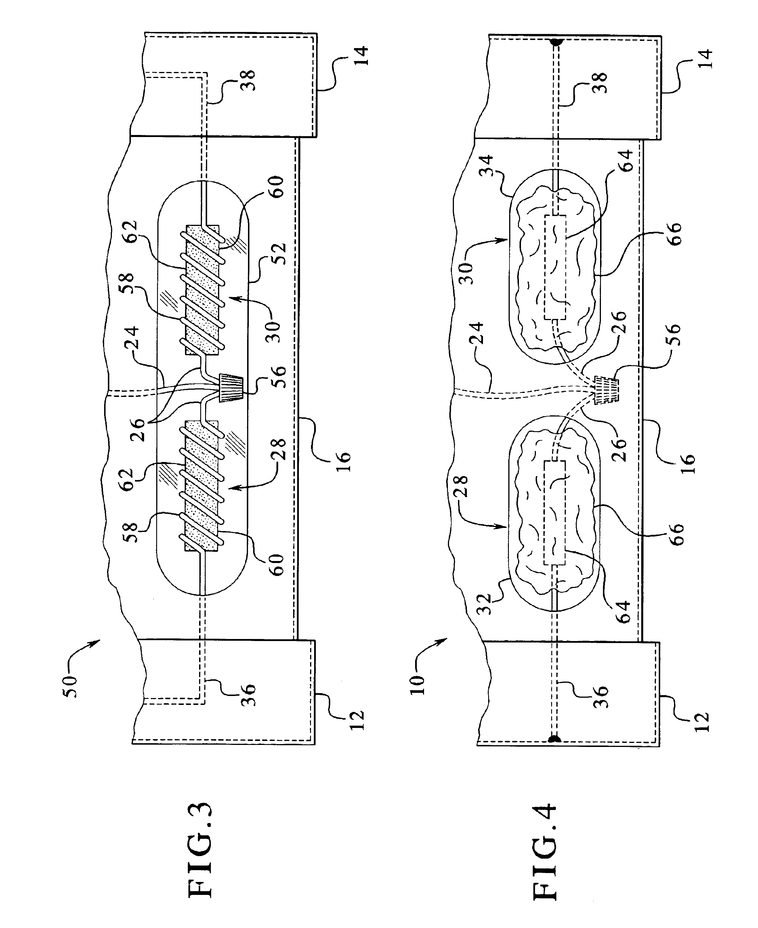
Referring now to the drawings and, in particular, to FIG. 1, a schematic cutaway of one embodiment of a fuse 10 having the diagnostic blown fuse indicator of the present invention is illustrated. The fuse 10 has a pair of cylindrical cup-shaped end caps 12 and 14, respectively. The end caps 12 and 14 are made of a suitably conductive material. A cylindrical body 16 is fixedly disposed between the end caps 12 and 14. The body 16 is made of a conventional insulating material. A portion of the end caps 12 and 14 and the body 16 has been cutaway for purposes of illustrating the dual element fuse circuit of the present invention.

The dual element fuse circuit includes a short circuit element 18 electrically communicating in series with a current overload element 20 (i.e., time delay element) and a heater element 22. For purposes of describing the present invention, it is sufficient to show the short circuit element 18 electrically communicating with the end cap 12 and the current overload...


PUM


Abstract

The present invention provides a blown fuse indicator. More specifically, the present invention provides a blown fuse indicator adapted for use with multiple element fuses, which provides a perceivable distinction between a blown fuse due to a current overload and a blown fuse due to a short circuit. To this end, in one embodiment of the present invention, a diagnostic blown fuse indicator is provided for a fuse having both a short circuit element and a current overload element. The indicator includes a short circuit indicator in electrical communication with the short circuit element, wherein the short circuit indicator provides visual indication of a short circuit condition. The indicator also includes a current overload indicator in electrical communication with the current overload element, wherein the current overload indicator provides visual indication of an overload condition.

Description

BACKGROUND OF THE INVENTION1. Field of the InventionThe present invention relates, generally, to fuses. More particularly, the present invention relates to fuses having indicators that visually change when the fuse blows.2. Description of the Prior ArtKnown fuses exist that provide dual elements, so that the fuses blow if a short circuit occurs or if a current overload condition occurs. One example of such a fuse includes a short circuit element in series with a current overload or time delay element. The combination of fuse elements electrically communicates with a pair of terminals, which respectively electrically communicate with a pair of electrically conductive rounded end caps. The end caps of the fuse typically snap-fit into well-known fuse clips.The short circuit element typically has a number of rows of slots in the metal or copper element. These rows of slots are commonly called bridges. A single, longer slot in the metal element exists between two of the bridges. The open...

Claims


Application Information

Patent Timeline
Patent Type & Authority Patents(United States)
IPC IPC(8): H01H85/00H01H85/32H01H85/30
CPCH01H85/32H01H85/30
Inventor STANEK, DANKENNEDY, JOHNKLINGER, LAWRENCE MARK
Owner LITTELFUSE INC
Why Eureka
Try Eureka