Electrical connector

Inactive Publication Date: 2005-03-01
CINCH CONNECTORS
View PDF48 Cites 24 Cited by
  • Summary
  • Abstract
  • Description
  • Claims
  • Application Information

AI Technical Summary

Benefits of technology

The electrical connector according to the present invention addresses these disadvantages, problems and other needs. The electrical connector can be used as an interposer in a fluid pressure sensor for an electronic anti-lock braking system, f

Problems solved by technology

Both of these designs yield a fairly large pa

Method used


Image

  • Electrical connector
  • Electrical connector
  • Electrical connector

Examples


Embodiment Construction

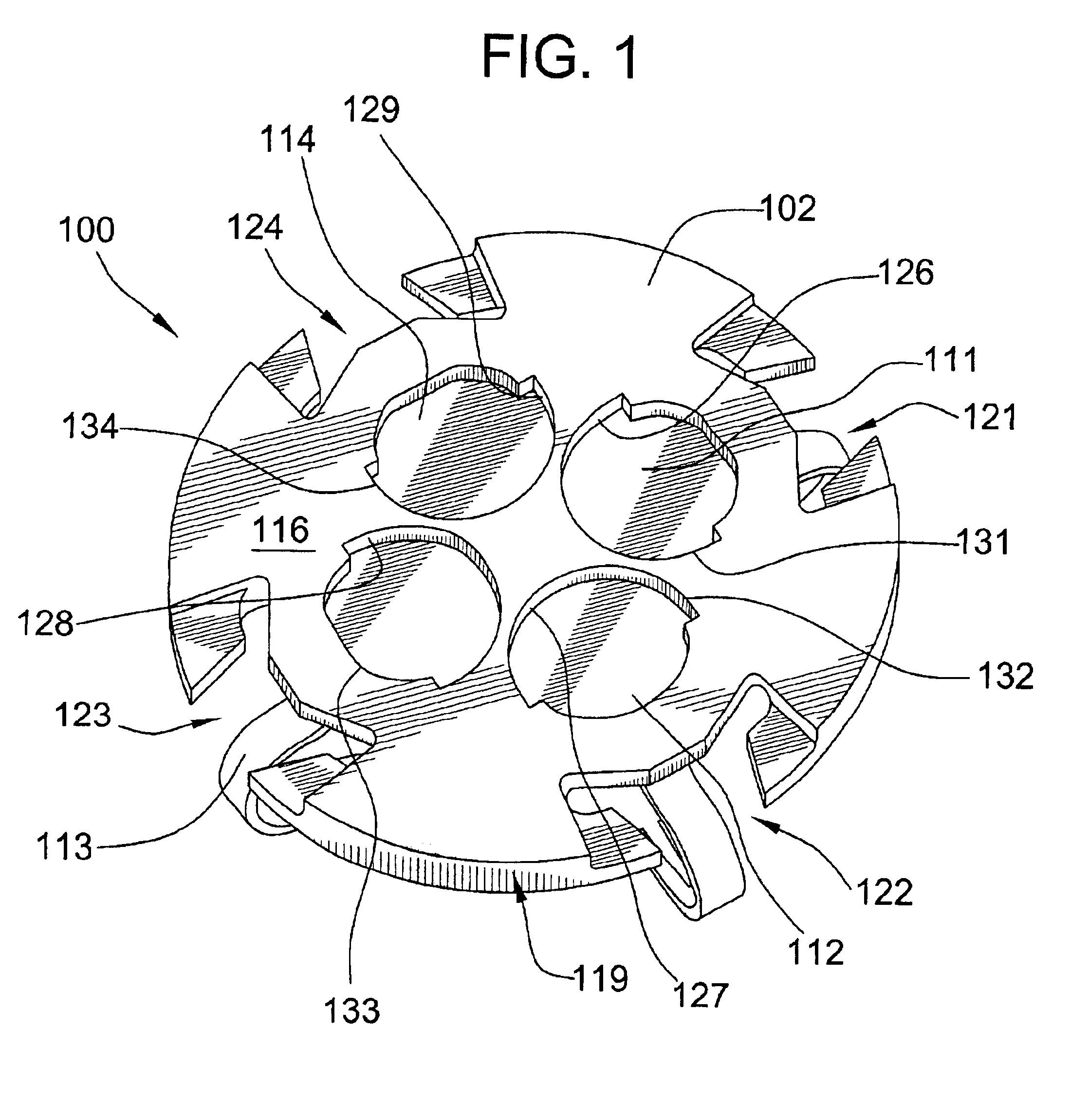
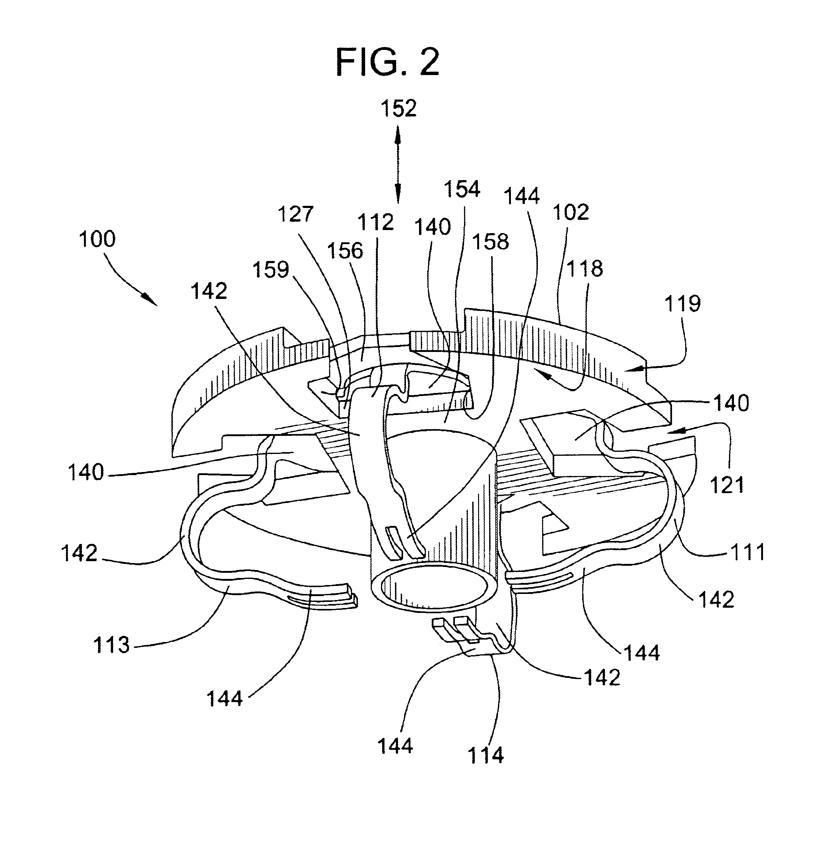
Turning now to the drawings, there is shown in FIGS. 1-6 an illustrative electrical connector 100 according to the present invention. The electrical connector 100 can provide a reliable mechanical pressure connection between itself and the component to which it is connected. The electrical connector 100 is compact, presenting a low-profile configuration. The electrical connector 100 can be used in a sensor, for example, as shown in FIG. 23.

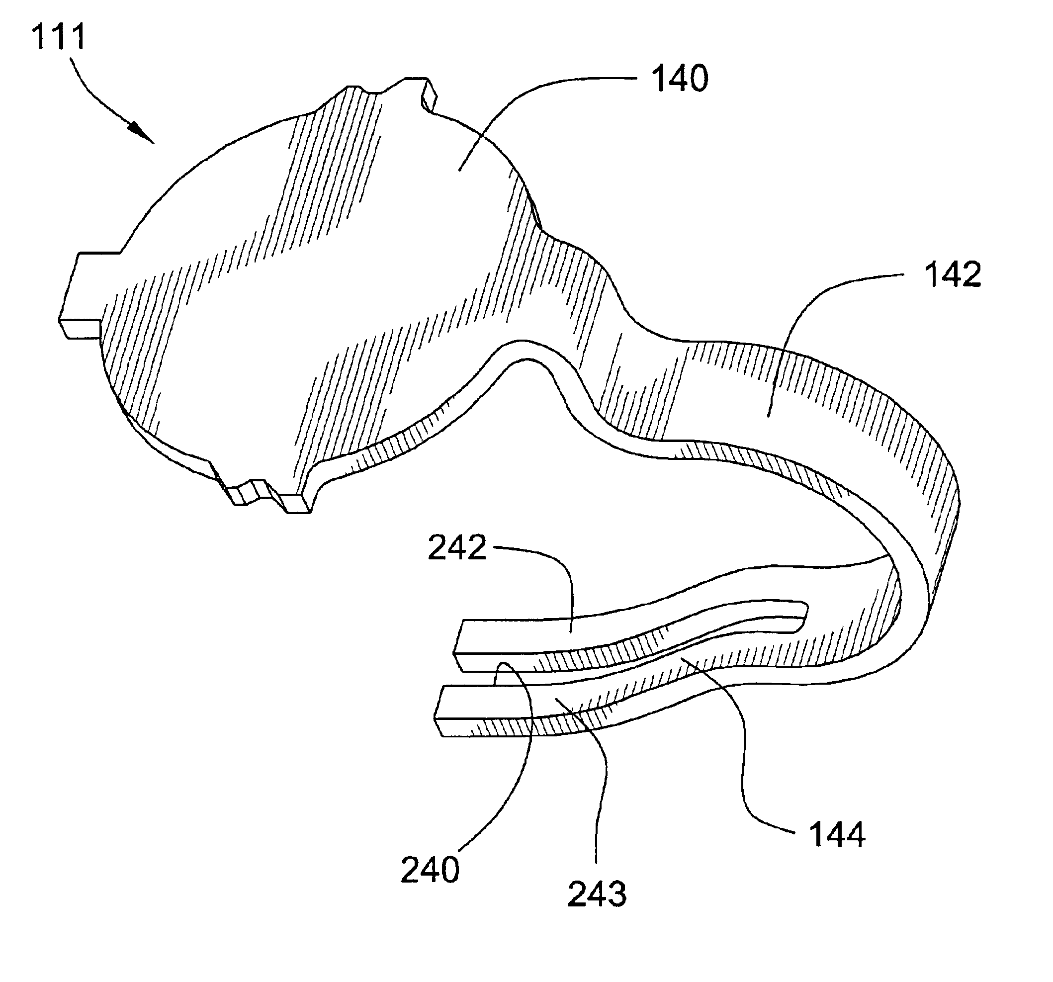
Referring to FIGS. 1-6, the connector 100 includes a housing 102 and a plurality of resiliently flexible electrical contacts 111, 112, 113, 114. The contacts 111, 112, 113, 114 are mounted to the housing 102. The contacts 111, 112, 113, 114 are electrically conductive and are resilient such that the contacts can be compressively engaged to exert a responsive contact pressure. The housing 102 can act as an electrical insulator. For example, the housing 102 can act to maintain the contacts in electrical isolation from each other.

Referring to FIGS. 1...


PUM


Abstract

An electrical connector is disclosed which includes a plurality of contacts mounted to a housing. The contact includes a first contact portion, a body portion, and a second contact portion. The first contact portion includes a tongue and a pair of retention members. The second contact portion can be bifurcated. The housing includes a plurality of insertion openings which each communicate with a respective cavity. Each cavity includes a pair of side walls, a pair of guide fins, an aperture communicating with a first surface of the housing, a seat, a support, and a slot. The first contact portions of the contacts are retentively engaged with the housing and are disposed in the respective cavities. The electrical connector can be used in an electrical device, such as, a sensor, for example. The electrical device can be mated to another electrical component.

Description

FIELD OF THE INVENTIONThis invention relates generally to electrical connectors and more particularly to an electrical connector for a sensor.BACKGROUND OF THE INVENTIONElectrical connectors are used to electrically connect one component to another component. Depending upon the particular application, an electrical connector may be required to satisfy certain criteria, such as, contact resistance, compliance or deflection distance, force required to achieve compliance, ease of assembly, and cost to manufacture.A sensor is a device which senses the state of an environment. For example, a sensor can sense the temperature or pressure. Sensors can be used in vehicles, such as automobiles, to sense the temperature of the engine or the pressure in a braking system. The sensor can be connected to a processing unit, such as, a computer, by wires and a printed circuit board. Economic considerations make it desirable for the sensor to be connected to the processing unit in a convenient and lo...

Claims


Application Information

Patent Timeline
IPC IPC(8): H01R13/428H01R13/66H01R13/24H01R13/22
CPCH01R13/2442H01R13/6658H01R13/428H01R13/2492
Inventor AUJLA, SHARANJIT S.ELKHATIB, HESHAM K.
Owner CINCH CONNECTORS
Why Eureka
Try Eureka