Golf club head

Inactive Publication Date: 2005-03-01
CALLAWAY GOLF CO
View PDF61 Cites 144 Cited by
  • Summary
  • Abstract
  • Description
  • Claims
  • Application Information

AI Technical Summary

Benefits of technology

One aspect of the present invention is a golf club head having a body composed of a lightweight,

Problems solved by technology

Most of the energy is transferred from the head to the golf ball, however, some energy is lost as a result of the collision.
However, this leads to greater deformations in the golf ball, and thus increases in the energy transfer problem.
A

Method used


Image

  • Golf club head
  • Golf club head
  • Golf club head

Examples


Embodiment Construction

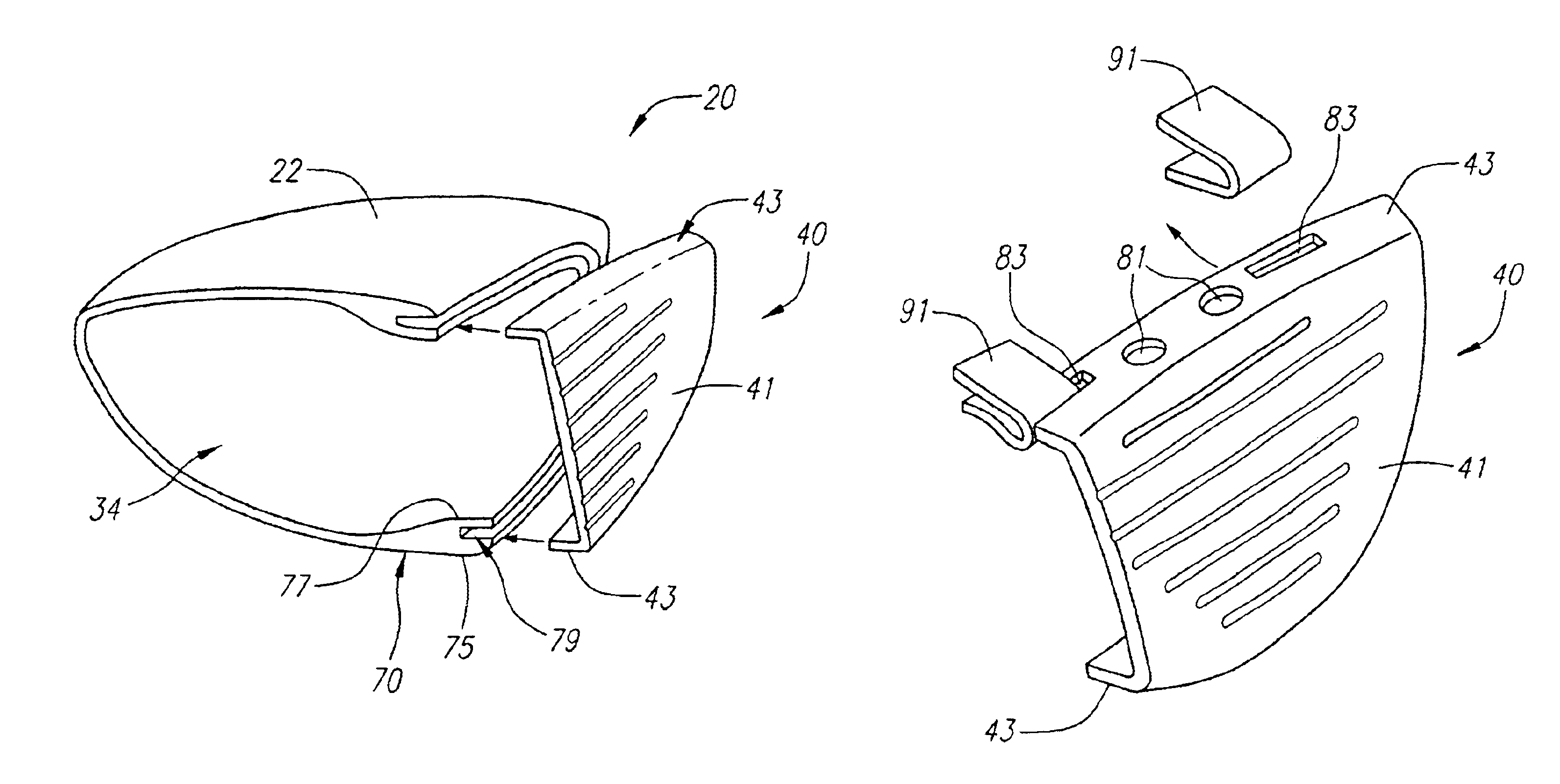
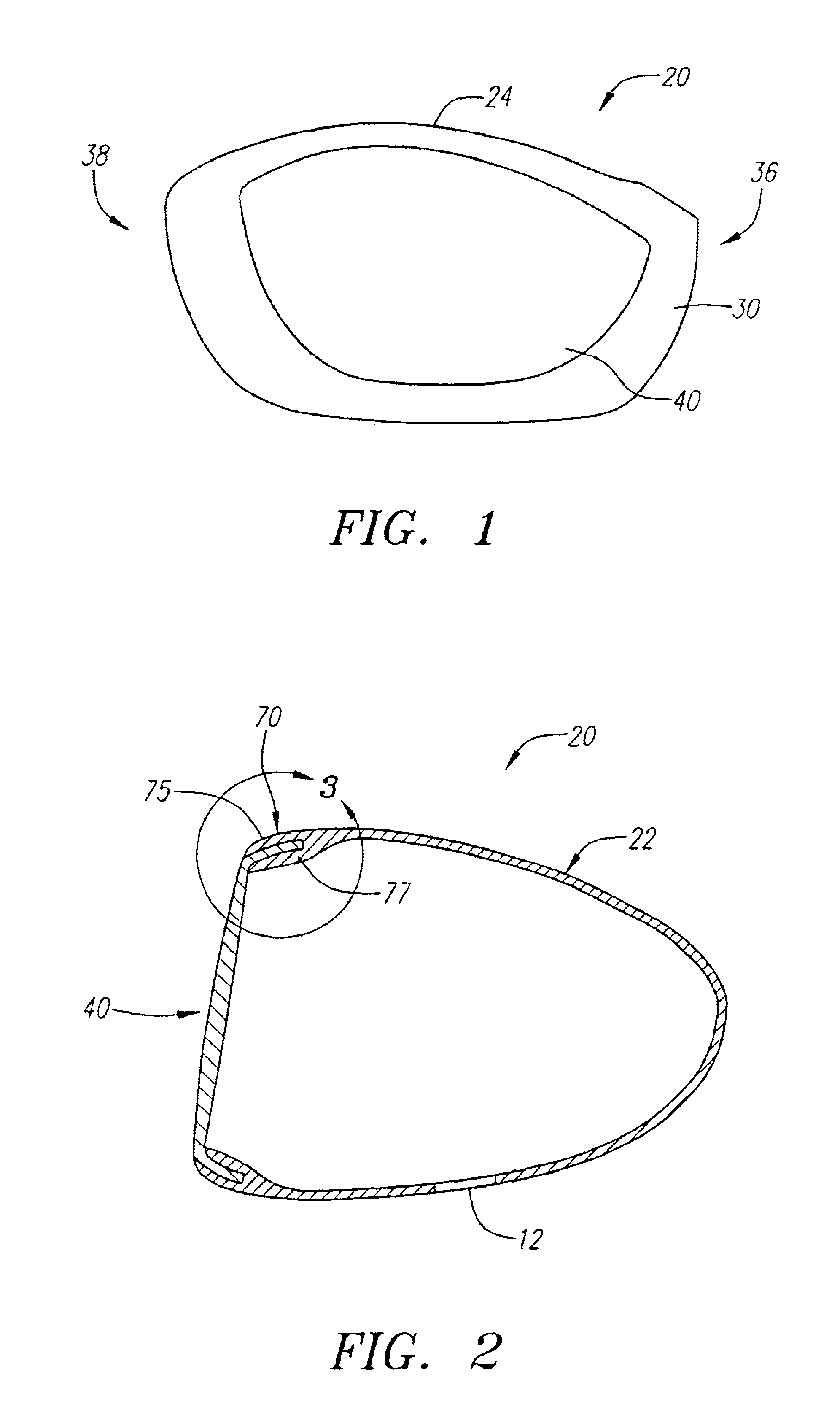
As shown in FIGS. 1-7, a golf club head is generally designated 20. The golf club head 20 preferably includes a body 22, a face component 40 and a rear weighting member 50. The golf club head 20 of the present invention has a high moment of inertia about the center of gravity, “CG”, for forgiveness, and a high coefficient of restitution to provide greater distance when striking a golf ball.

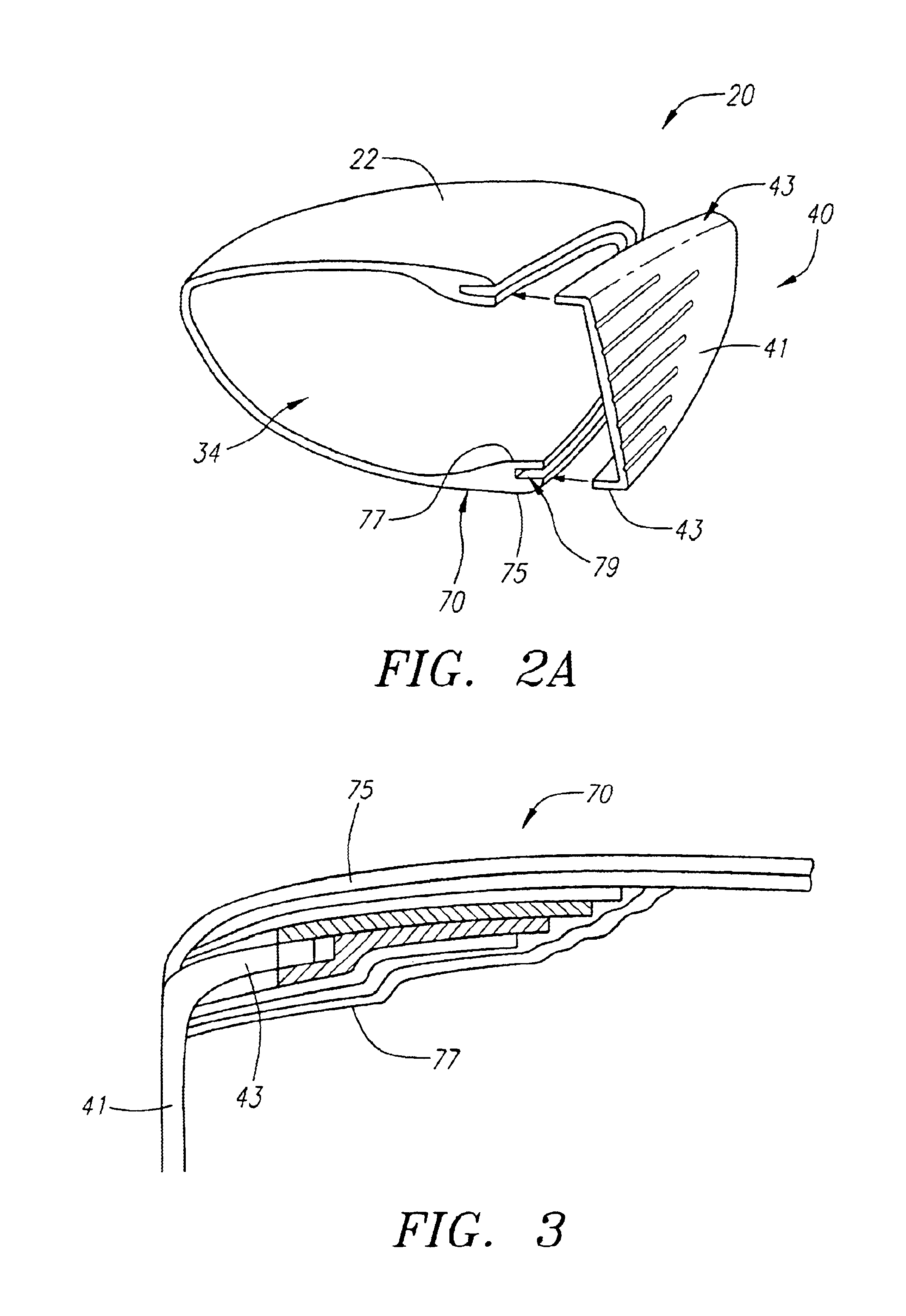
The body 22 has a crown 24, a sole 26, a ribbon 28, and a front wall 30 with an opening 32 and preferably an outer edge 75 and an inner edge 77 defining a groove 79. The ribbon 28 preferably has an aft-recess 52 located opposite of the striking plate insert 40. The body 22 preferably has a hollow interior 34. The golf club head 20 has a heel end 36, a toe end 38 an aft end 37. The body 22 is preferably composed of a non-metal material, preferably a composite material such as a continuous fiber pre-preg material (including thermosetting materials or a thermoplastic materials for the resin). Other m...


PUM


Abstract

A golf club head (20) having a body (22) with a front wall (30) with an opening (32) and a face component (40) is disclosed herein. The face component (40) has a striking plate 41 and a return portion 43. The return portion (43) creates a sandwich structure (70) with edges (75 and 77) of the body (22). The body (22) is preferably composed of a light weight non-metal material. The golf club head (20) preferably has a volume between 300 cubic centimeters and 600 cubic centimeters. The golf club head (20) preferably has a mass between 105 grams and 300 grams.

Description

FEDERAL RESEARCH STATEMENT[Not Applicable]BACKGROUND OF INVENTION1. Field of the InventionThe present invention relates to a golf club head with a metal striking plate insert. More specifically, the present invention relates to a golf club head with a non-metal body and a metal striking plate insert.2. Description of the Related ArtWhen a golf club head strikes a golf ball, large impacts are produced that load the club head face and the golf ball. Most of the energy is transferred from the head to the golf ball, however, some energy is lost as a result of the collision. The golf ball is typically composed of polymer cover materials (such as ionomers) surrounding a rubber-like core. These softer polymer materials having damping (loss) properties that are strain and strain rate dependent which are on the order of 10-100 times larger than the damping properties of a metallic club face. Thus, during impact most of the energy is lost as a result of the high stresses and deformations of t...

Claims


Application Information

Patent Timeline
IPC IPC(8): A63B53/04A63B59/00
CPCA63B53/04A63B53/0466A63B59/0092A63B2053/0408A63B2053/0412A63B2053/0416A63B2053/0462A63B59/0088A63B2209/00A63B2209/02A63B2053/0433A63B2053/0458A63B60/54A63B60/50A63B53/0412A63B53/0458A63B53/0462A63B53/0408A63B53/0416A63B53/0433A63B60/00
Inventor LEE, KYU WANG
Owner CALLAWAY GOLF CO
Why Eureka
Try Eureka