Laparoscopic lifter apparatus and method

Inactive Publication Date: 2005-03-01
PITTMAN GREGORY R
View PDF1 Cites 43 Cited by
  • Summary
  • Abstract
  • Description
  • Claims
  • Application Information

AI Technical Summary

Benefits of technology

Another principal objective of the present invention is to provide a laparoscopic surgical instrument that greatly benefits the removal of solid organs, such as a spleen or a kidney, having a narrow hilum where hilar dissection can be the most difficult part of a procedure.
Another objective of the present invention is to provide a laparoscopic lifting and holding instrument that can be manipulated to fit under an organ and gently lift the organ with minimal danger of organ damage and of subsequent operating field contamination.
Still another objective of the present invention is to markedly improve safety during laparoscopic procedures by decreasing operating time generally, and specifically by reducing the possibility of having to convert a laparoscopic procedure to an open procedure.
Yet, another objective of the present invention is to reduce surgical expenses by enhancing an operator's ability to do a procedure laparoscopically rather than through a large incision.
In brief, the present invention comprises a laparoscopic surgical instrument, mainly a laparoscopic lifter apparatus which includes a manipulating handle used to retract or eject flexible, band like arms having blunt ends into or out of a rigid tubular rod, the arms assuming opposing arcuate shapes upon ejection from the tubular rod and the arm's blunt ends separated by a gap so easy laparoscopic instrument

Problems solved by technology

Most laparoscopic surgical instruments are designed to grasp tissue in opposing rough surfaced contact jaws terminating in irregular shapes not useful for organ manipulation and having the potential to cause organ perforation.
The above described inventions a

Method used


Image

  • Laparoscopic lifter apparatus and method
  • Laparoscopic lifter apparatus and method
  • Laparoscopic lifter apparatus and method

Examples


Example

DETAILED DESCRIPTION OF THE DRAWINGS

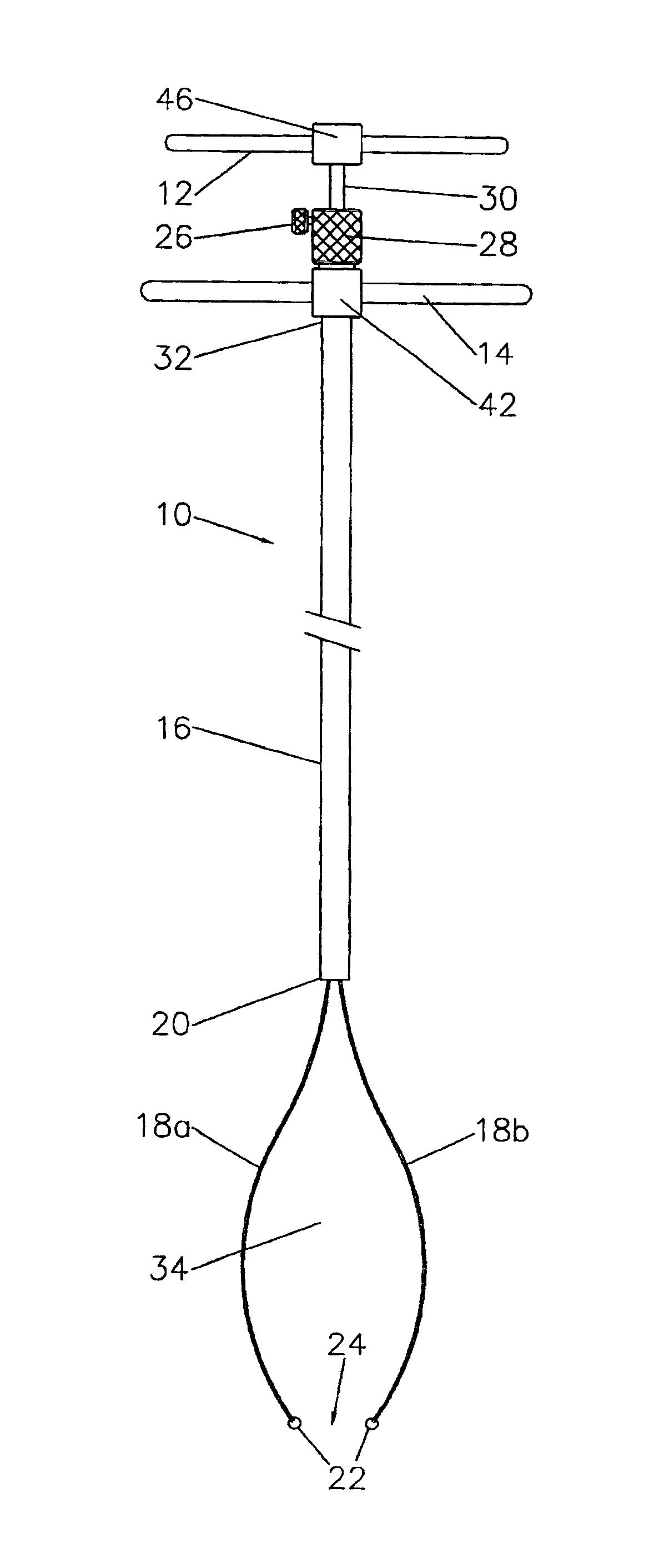
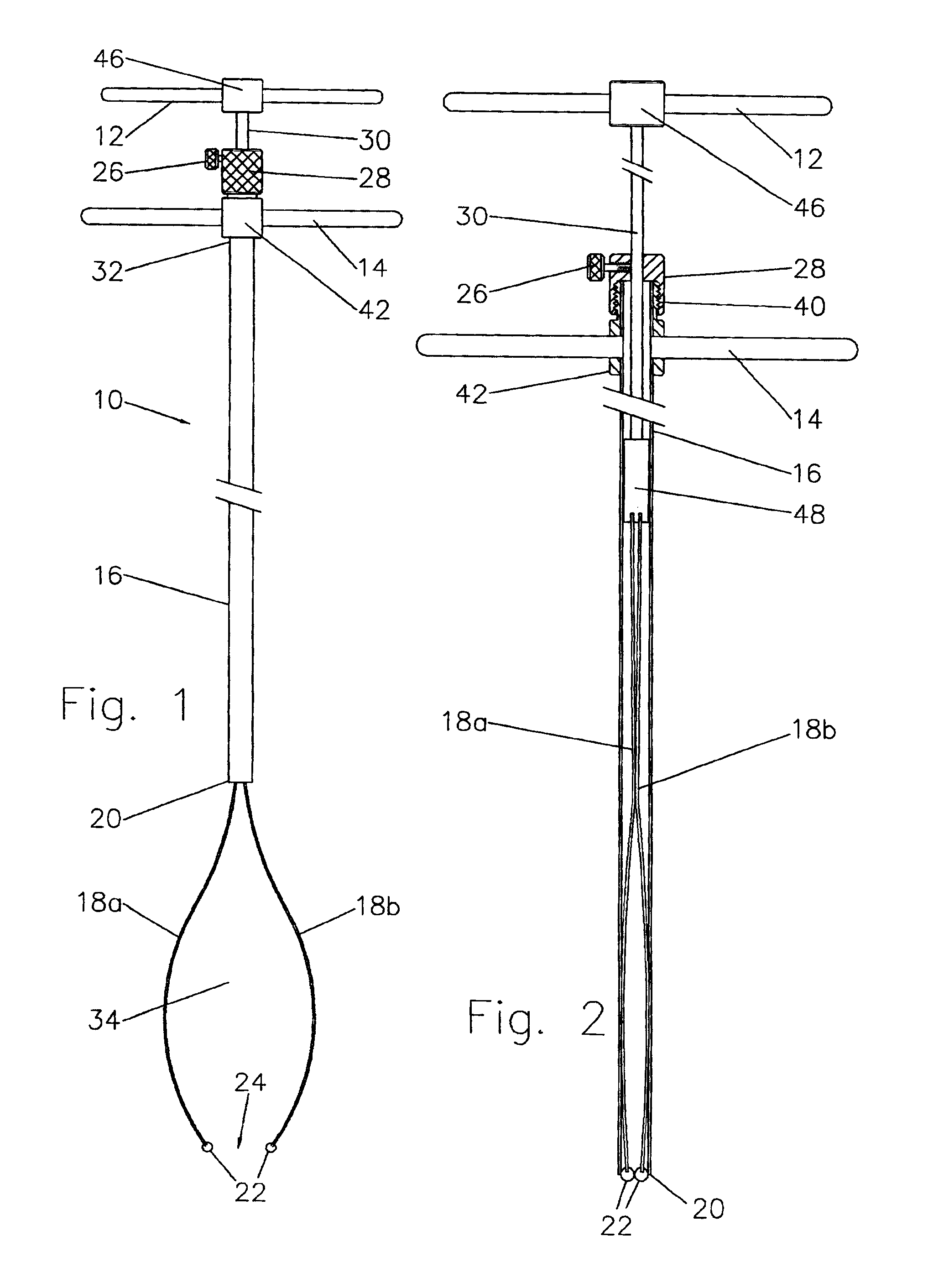
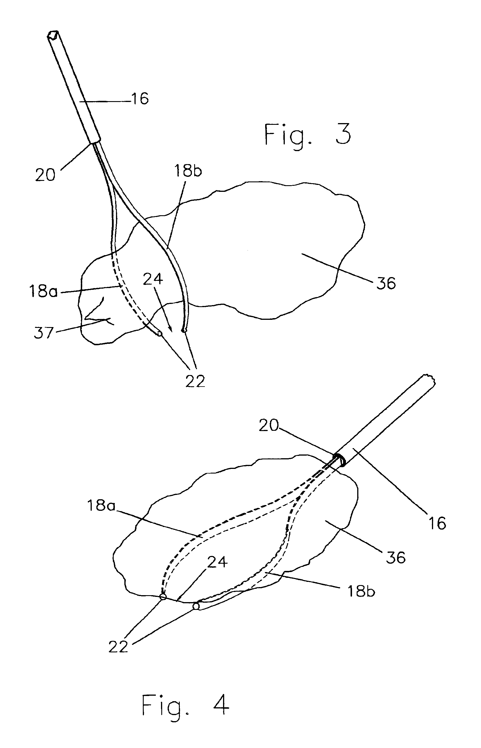
Referring now to the drawings, FIG. 1 is a plan view of a surgical instrument, mainly an assembled laparoscopic organ lifter apparatus 10 comprising a first manipulating bilateral handle 12, a second holding and steadying bilateral handle 14, a strong, rigid tubular rod 16 housing more than one band like flexible arm 18a, 18b. Arms 18a, 18b exit tubular rod 16 at a distal end 20 and assume oppositely disposed preformed arcuate shapes. The band like arms 18a, 18b are mirror images of each other equal in length, width and depth, each arm 18a, 18b having a width substantially three to four times greater than the depth and each arm 18a, 18b ending in a blunt sphere 22, the blunt spheres 22 spaced apart to define an opening 24. Each arm 18a, 18b has a uniform width throughout its length. After arms 18a, 18b are extended to achieve a proper lifting position, a locking screw 26 retained in a threaded opening in an internally threaded ring 28 can be tight...


PUM


Abstract

A surgical instrument, mainly a laparoscopic organ lifter apparatus and method comprising a flexible arm component having a first manipulating bilateral handle with a central element securing a solid rod terminating in a connector piece holding flexible arms, the solid rod passing through an internally threaded ring housing a locking screw and a tubular rod component having a hollow rod with a proximal hollow externally threaded coupler disposed to receive the internally threaded ring when the hollow rod houses the flexible arms component. To lift and hold an organ, an operator thrusts the first bilateral handle toward the hollow rod proximal end thereby extending the flexible arms outside a hollow tube distal end where the arms assume an arcuate shape appropriate to lift and hold steady an organ such as a spleen.

Description

BACKGROUND OF THE INVENTION1. Field of the InventionThe present invention relates to surgical instruments for use during laparoscopic surgery. More particularly, the invention is directed to a surgical tool designed to gently manipulate and lift an organ thereby providing a means for allowing safe organ release from body cavity constraints and then, expedient organ removal.2. Description of the Prior ArtIn order to perform laparoscopic surgery, surgical instruments are inserted through discrete openings in a patient's abdominal cavity eliminating a need for lengthy incisions accompanied by excess patient trauma and surgical complications. Most laparoscopic surgical instruments are designed to grasp tissue in opposing rough surfaced contact jaws terminating in irregular shapes not useful for organ manipulation and having the potential to cause organ perforation.In U.S. Pat. No. 6,013,095, an endoscopic grasping tool has grasping pieces with tip end portions formed into inwardly bent ...

Claims


Application Information

Patent Timeline
IPC IPC(8): A61B17/00A61B17/02A61B17/28A61B17/30
CPCA61B17/00234A61B17/0218A61B17/30A61B17/0281A61B2017/2917A61B17/29A61B17/2833
Inventor PITTMAN, GREGORY R.
Owner PITTMAN GREGORY R
Why Eureka
Try Eureka