
Carpet of wave energy conversion (CWEC)

a technology of wave energy and transformer, which is applied in the field of transformer of wave energy, can solve the problems of only working photovoltaic systems and significant hazards to shipping

Inactive Publication Date: 2016-04-21
RGT UNIV OF CALIFORNIA
View PDF11 Cites 6 Cited by
  • Summary
  • Abstract
  • Description
  • Claims
  • Application Information

AI Technical Summary

Benefits of technology

The CWEC is a new type of wave energy converter that can be placed in non-open water locations. It uses a synthetic seabed carpet and a power take off (PTO) system to convert the energy from overtopping waves into working energy. This can be used to generate electricity or store it for later use. Compared to existing wave energy converters, the CWEC is safer and can operate under extreme sea conditions. It can also be used to create safe havens for fishermen or protect shores and harbors from strong storm waves. Additionally, the high-pressure seawater can be used to supply a reverse osmosis desalination plant or for direct energy conversion to electricity. The harvested energy can also be stored without significant losses and later converted to electricity at times with higher demand and higher utility prices.

Problems solved by technology

Some traditional wave energy extraction systems use windmill-styled blades that are injurious to marine life, and pose significant hazards to shipping.
Photovoltaic systems only work when the sun is shining.

Method used


Image

  • Carpet of wave energy conversion (CWEC)
  • Carpet of wave energy conversion (CWEC)
  • Carpet of wave energy conversion (CWEC)

Examples


Embodiment Construction

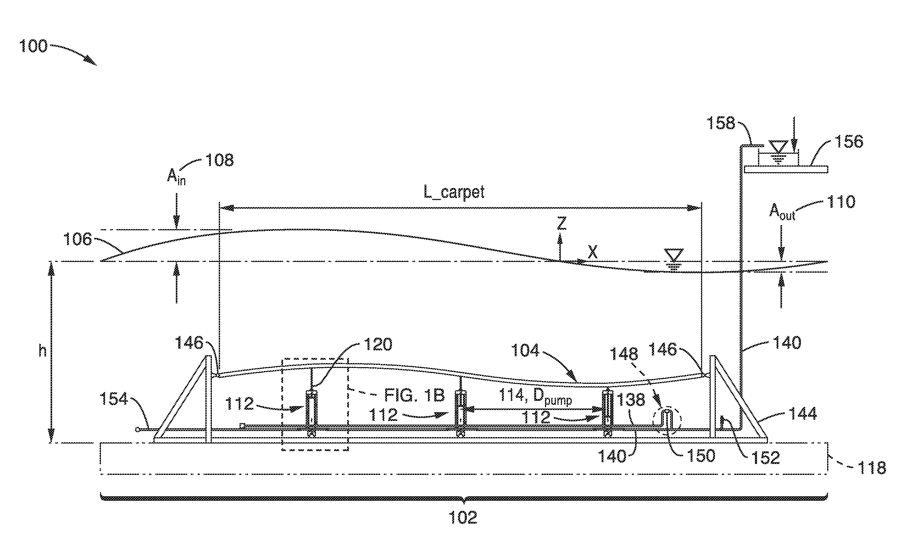
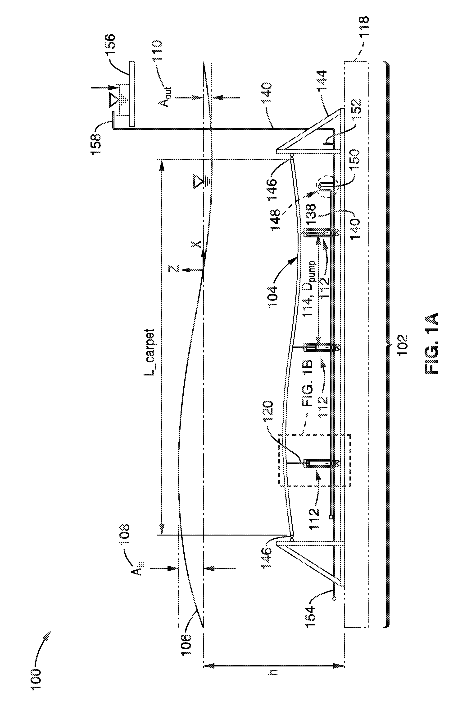
[0036]Refer now to FIG. 1A, which is a simplified side view 100 embodiment of a Carpet of Wave Energy Conversion (CWEC) 102. The CWEC 102 begins with an absorber carpet 104 that interacts with an incoming wave 106 to extract energy from the wave 106. The result is an incoming wave 106 of amplitude Ain 108 exiting the CWEC 102 with a diminished output amplitude of Aout 110. The difference between the Ain 108 and Aout 110 relates to the energy extracted from the wave 106 by the CWEC 102.

[0037]A wave absorption efficiency may be defined as a ratio

Ein-EoutEin

where the outgoing energy Eout of the wave 106 is related to Aout 110, and the incoming energy Ein of the wave is related to Ain 108. The CWEC 102 may have very high wave absorption efficiencies, approaching unity.

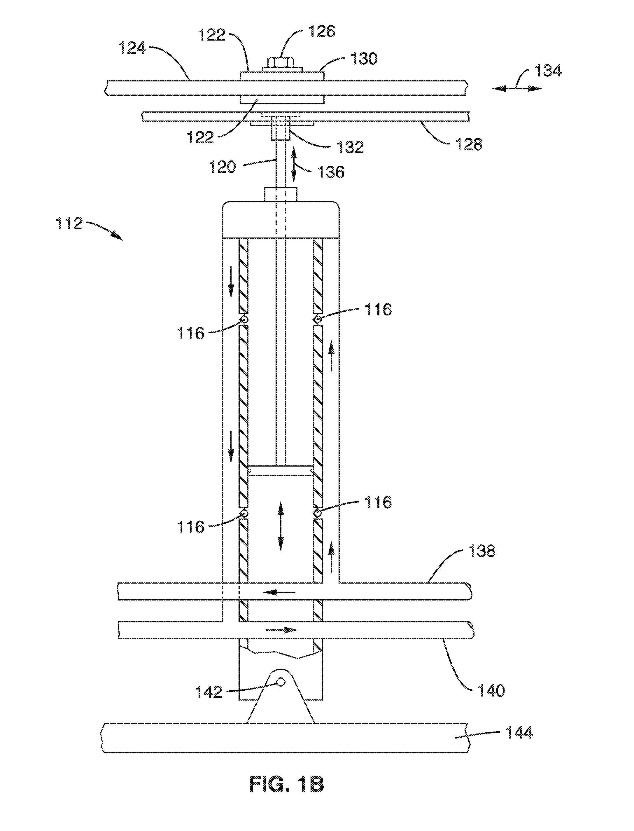
[0038]For the CWEC 102 to generate power, the absorber carpet 104 couples incoming wave 106 energy to one or more (preferably double action) pumps 112 spaced apart by Dpump 114. Each pump 112 has one or more check valves 1...


PUM

PropertyMeasurementUnit
Young's moduliaaaaaaaaaa

Abstract

A carpet of wave energy conversion (CWEC) device mechanically couples an absorber carpet to one or more energy converters, thereby allowing for wave energy extraction from passing waves. The absorber carpet may be flexible material of a composite material that has a low elastic modulus in a longitudinal direction (to allow for stretching), and a relatively higher elastic modulus in a transverse direction (to better couple energy from wave to converters). Such designs have minimal wave reflections and high efficiencies within a relatively short extent of deployment. The resultant converted useful energy is available as either: 1) mechanical power including direct desalinization or electrical production; or 2) hydraulic power for a number of applications (including hydraulically powered motors supplying power to powered devices including generators), or pumping of the wave medium under pressure to an alternate location for irrigation or energy storage.

Description

CROSS-REFERENCE TO RELATED APPLICATIONS[0001]This application is a 35 U.S.C. §111(a) continuation of PCT international application number PCT / US2014 / 035056 filed on Apr. 22, 2014, incorporated herein by reference in its entirety, which claims priority to, and the benefit of, U.S. provisional patent application Ser. No. 61 / 814,379 filed on Apr. 22, 2013, and which claims priority to, and the benefit of, U.S. provisional patent application Ser. No. 61 / 974,432 filed on Apr. 2, 2014. Priority is claimed to each of the foregoing applications.[0002]The above-referenced PCT international application was published as PCT International Publication No. WO 2014 / 176293 on Oct. 30, 2014, which publication is incorporated herein by reference in its entirety.STATEMENT REGARDING FEDERALLY SPONSORED RESEARCH OR DEVELOPMENT[0003]Not ApplicableINCORPORATION-BY-REFERENCE OF COMPUTER PROGRAM APPENDIX[0004]Not ApplicableNOTICE OF MATERIAL SUBJECT TO COPYRIGHT PROTECTION[0005]A portion of the material in ...

Claims


Application Information

Patent Timeline
Patent Type & Authority Applications(United States)
IPC IPC(8): F03B13/18
CPCF03B13/187F03B13/188F05B2240/95F05B2240/97F05B2280/4003F05B2280/4004F05B2280/5001Y02E10/30F03B13/1885F03B13/22
Inventor ALAM, MOHAMMAD-REZALEHMANN, MARCUSSHAKERI, MOSTAFA
Owner RGT UNIV OF CALIFORNIA
Learn More