
Method and apparatus for the modeling and synthesis of harmonic distortion

a technology of harmonic distortion and modeling and synthesis, applied in the direction of instruments, electrophonic musical instruments, gain control, etc., can solve the problems of harsh quality, lack of digital distortion effects, and undesirable harmonic distortion types

Inactive Publication Date: 2003-01-07
JACKSON DOUGLAS L
View PDF10 Cites 110 Cited by
  • Summary
  • Abstract
  • Description
  • Claims
  • Application Information

AI Technical Summary

Benefits of technology

It is an additional object of the invention to provide a distortion modeling and synthesis method that facilitates efficient storage of distortion models for later recall and usage.
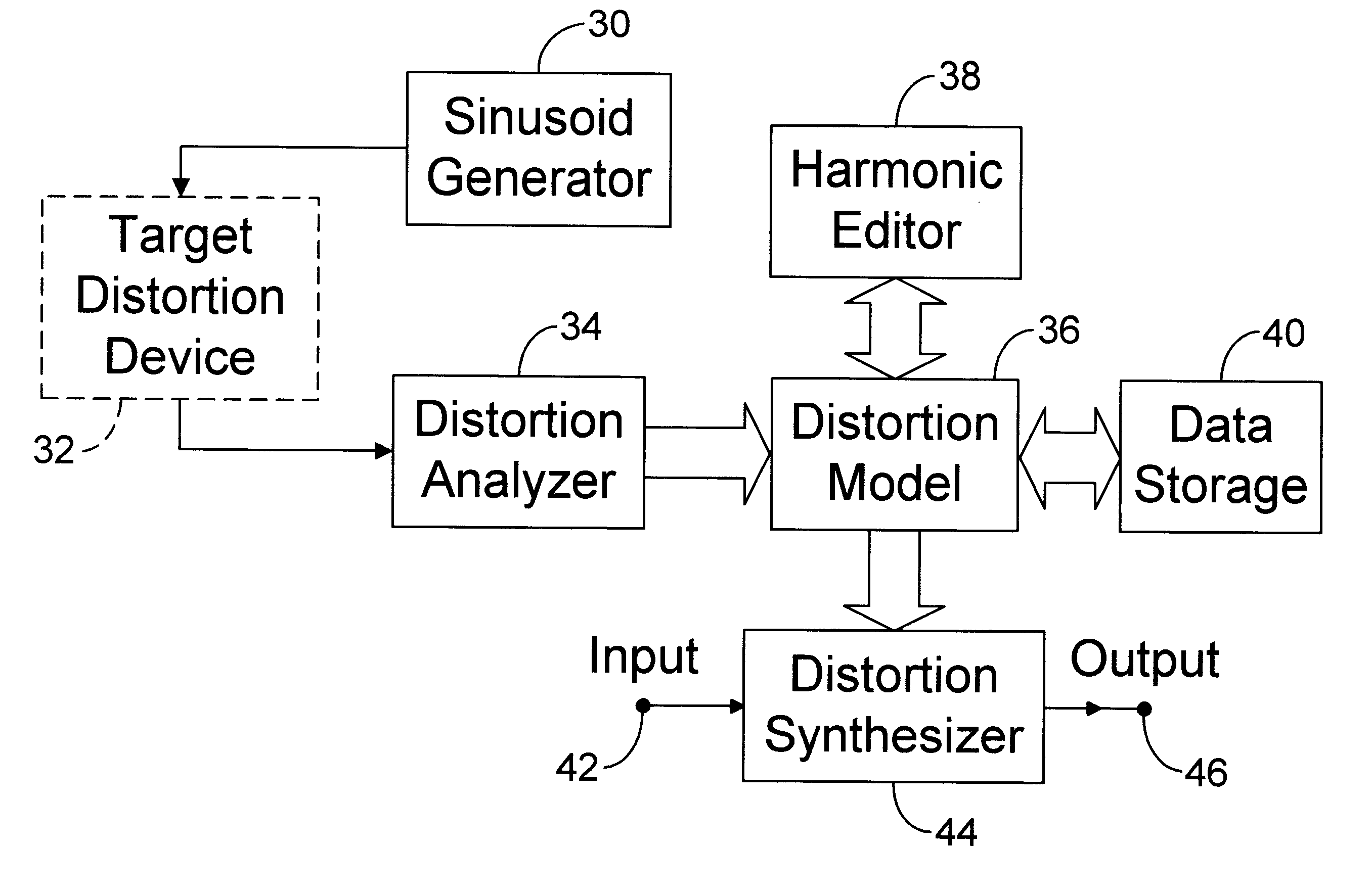
Several advantages are realized by the modeling and synthesis approach to digital distortion as implemented in my invention. Foremost is the high accuracy with which the non-linearity of a distortion device is reproduced. Another advantage is the versatility of the invention. Rather than being a method for synthesizing the effect of one specific type of distortion device, the present invention provides a general method capable of synthesizing the effects of different types of distortion devices. The modeling method can extract the static non-linear transfer characteristics of a device even if its non-linear element can only be accessed dynamically, such as with analog recording tape. A further advantage is that the distortion model's components directly relate to the way humans perceive sound; that is, by the sound's harmonic content. As such, the distortion model can be modified to alter its sonic characteristics predictably. A distortion model contains a relatively small amount of data, typically less than one hundred numeric values, allowing for efficient storage of multiple models in a data-storage device.
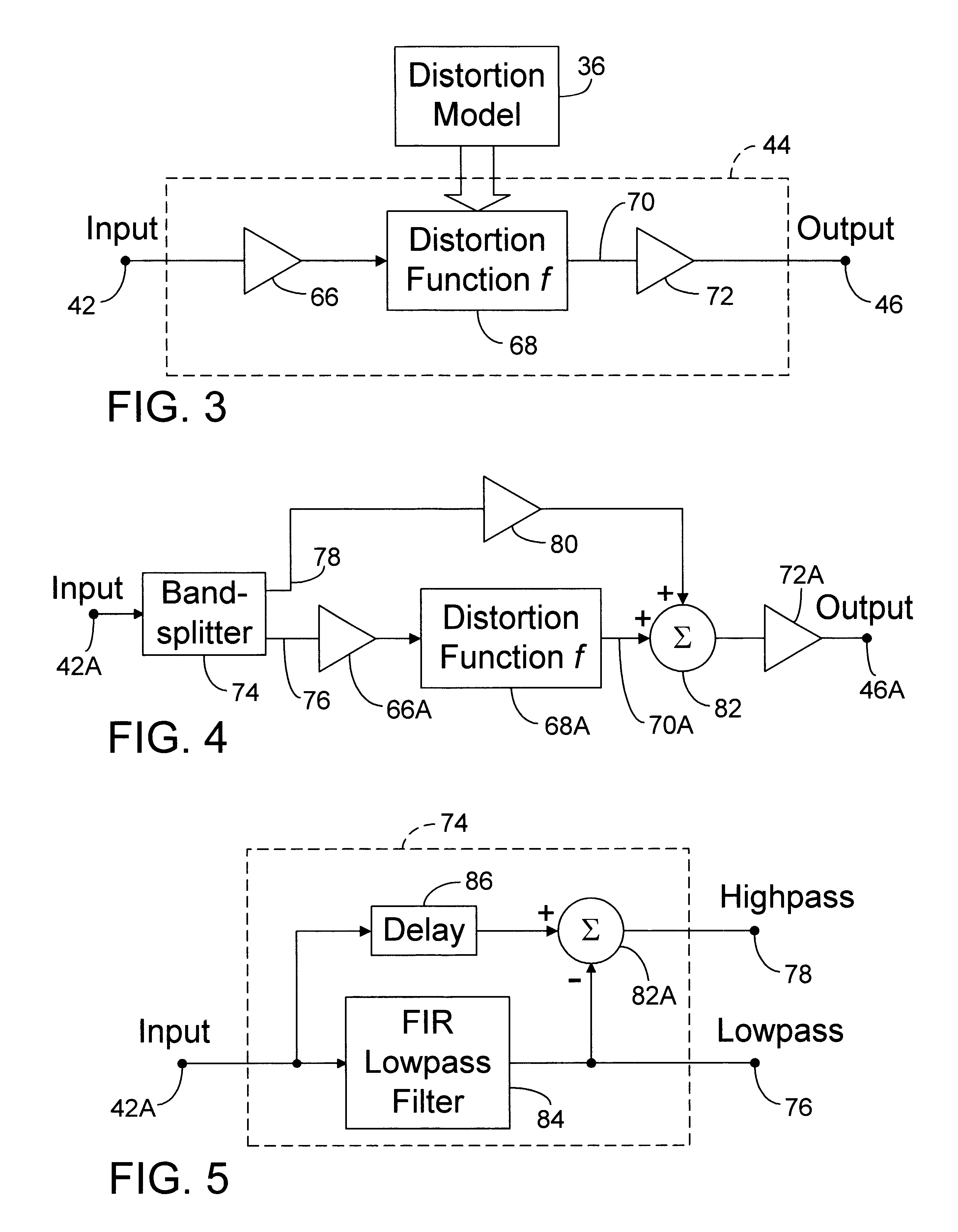
A problem that occurs when generating harmonic distortion digitally is the production of aliasing noise. The frequencies of some of the harmonics added to a signal by the non-linear distortion process may exceed one-half of the sampling rate. Consequently, those harmonics fold back into the audible signal as aliasing noise. The ability to modify the distortion model of my invention has the further advantage of making it possible to reduce aliasing noise by eliminating the upper harmonics from the model. The distortion synthesizer contains further enhancements specifically for controlling aliasing noise. A frequency bandsplitter separates the input signal into a low frequency signal and a high frequency signal. Distortion is applied only to the low frequency signal, which is subsequently recombined with the high frequency signal. The bandlimiting action of the bandsplitter creates spectral headroom that permits the addition of harmonics without causing aliasing noise. To apply distortion to the full bandwidth of the input signal without causing aliasing noise, sampling-rate conversion is used. The distortion synthesizer provides mechanisms for increasing and decreasing the sampling rates of digital signals. Before applying the distortion, the input signal is converted to a higher sampling rate to create spectral headroom for accommodating the added harmonics. After applying the distortion, the signal is converted back to the original sampling rate. The conversion process removes the added harmonics having frequencies that exceed one-half of the reduced sampling rate, thereby preventing aliasing noise. Combining the bandsplitter with sampling-rate conversion further extends the spectral headroom.

Problems solved by technology

When processing audio signals, however, some types of harmonic distortion are desirable.
Digital distortion effects generally lack the accuracy needed to be convincing replacements for their analog counterparts and tend to possess a harsh quality that reveals their digital origins.
They do not emulate the distortion characteristics of any actual analog distortion device but instead provide only some characteristics of a generalized class of distortion device.
They also do not provide any method of suppressing the aliasing noise that can result when performing a non-linear operation in a digital system.
It does not provide any method of suppressing the aliasing noise that can result when performing a non-linear operation in a digital system.
The segmentation of the distortion curve generates high harmonics that are usually undesirable and further add to the aliasing noise.
It does not provide any method of suppressing the aliasing noise that can result when performing a non-linear operation in a digital system.
However, the focus is on the direct synthesis of musical instrument sounds and, as such, offers no method for applying a distortion effect to digital audio signals.
The digital waveshaping functions described are limited to the synthesis of musical instrument sounds when applied to a sinusoidal waveform.
No method is offered for generating a waveshaping function that would emulate another distortion device when applied to a digital audio signal.
As such, no method is offered for generating a waveshaping function that would emulate another distortion device.
No method is provided for suppressing the aliasing noise that can result when performing a non-linear operation in a digital system.
Although they do apply a form of distortion to a digital signal, their non-linear processing is specifically for video and is irrelevant for audio.
Besides the limitations already stated, none of the prior art perform direct analyses of existing distortion devices for deriving methods or models that can be used to emulate the distortion devices.
A problem that occurs when generating harmonic distortion digitally is the production of aliasing noise.

Method used


Image

  • Method and apparatus for the modeling and synthesis of harmonic distortion
  • Method and apparatus for the modeling and synthesis of harmonic distortion
  • Method and apparatus for the modeling and synthesis of harmonic distortion

Examples


example graphs

FIGS. 19a through 21c are graphs that demonstrate some of the basic features of the present invention. The graphs depict actual examples produced by the prototype of the present invention.

FIG. 19a is a graph of an arbitrary transfer function created as described in the Arbitrary Distortion Model section. The bar graph in FIG. 19b shows the amplitudes of the first fifty-two harmonics of the distortion model derived from the transfer function. The angularity of the transfer function accounts for the higher harmonics of the distortion model. The bar graph in FIG. 19c shows the harmonic amplitudes of a modified version of the distortion model shown in FIG. 19b. The harmonics above the nineteenth are eliminated. The phases of the harmonics are unchanged. FIG. 19d shows a graph of a distortion function using the modified version of the distortion model. Note the smooth curves in comparison to FIG. 19a. When the distortion model retains two hundred or more harmonics, a graph of the distort...


PUM


Abstract

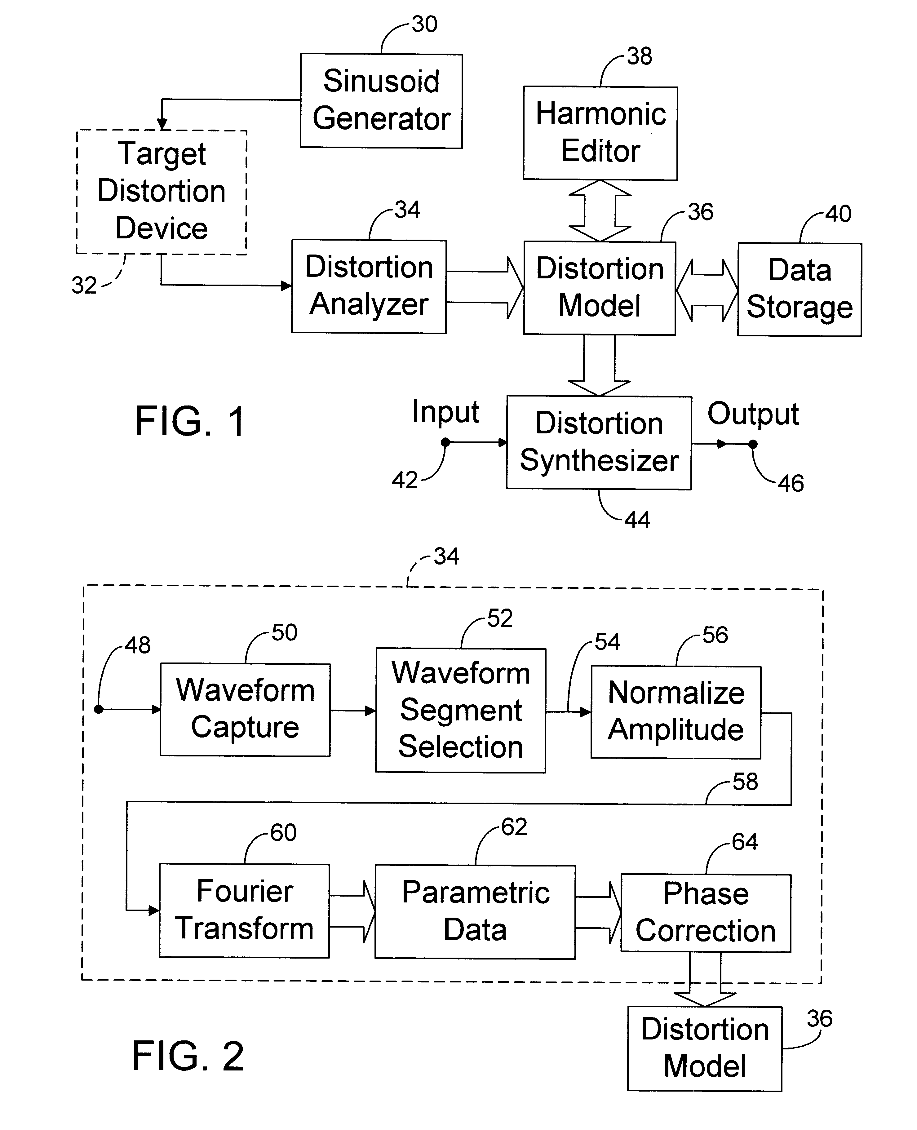
Distortion modeling produces distortion models for use by a distortion synthesizer to synthesize the harmonic distortion effects of audio distortion devices. A sinusoidal waveform is distorted by an audio distortion device and analyzed using a Fourier transform to produce a distortion model comprising harmonic amplitude and phase parameters. A phase correction process compensates for phase shifts induced by the audio distortion device. The distortion synthesizer uses a distortion function that distorts a digital audio signal according to the distortion model. The distortion model can be modified to alter the distortion effect and can be stored in a data-storage device for later retrieval. A frequency bandsplitter and signal mixer allow the distortion effect to be applied only to the low frequency content of the digital audio signal, thus providing spectral headroom to suppress the production of aliasing noise. Aliasing-noise suppression is provided for a full-bandwidth signal by up-converting the sampling rate of the signal before applying the distortion function and down-converting the sampling rate afterwards. A process is provided to remove the direct-current component that may be induced into the signal by the distortion function.

Description

This invention relates to digital audio signal processing, specifically to an improved method for imparting a harmonic distortion effect to a digital audio signal.BACKGROUND--DESCRIPTION OF PRIOR ARTMost electronic systems that process (amplify, transmit, etc.) analog signals are designed to minimize the amount of harmonic distortion added to the signal. When processing audio signals, however, some types of harmonic distortion are desirable. Audio professionals, musicians, and audiophiles widely pursue the sonic characteristics of vacuum tubes, analog recording tape, transducers, and a variety of solid-state distortion devices. Harmonic distortion due to non-linear transfer characteristics, either inherent or deliberately induced, is mainly responsible for imparting the desirable effect.The progress of digital recording and signal processing technologies is at a point where most audio signal processing tasks can be performed satisfactorily in the digital domain. One notable exceptio...

Claims


Application Information

Patent Timeline
Patent Type & Authority Patents(United States)
IPC IPC(8): G10H1/06G10H1/16G10H3/00G10H1/12G10H3/18H04B1/28
CPCG10H1/125G10H1/16G10H3/187H04B1/0003H04B1/0025G10H2250/115H04B1/28G10H2250/235G10H2250/545G10H2250/191
Inventor JACKSON, DOUGLAS L.
Owner JACKSON DOUGLAS L
Learn More