
Three-dimensional display system: apparatus and method

a three-dimensional display and apparatus technology, applied in the field of three-dimensional display, can solve the problems of poor three-dimensional display system production, not having a practical system which may be considered to offer all the capabilities necessary, and limiting the degree of success so far, so as to achieve efficient storage and display of images

Inactive Publication Date: 2001-12-11
TAMIRAS PER PTE LTD LLC
View PDF17 Cites 119 Cited by
  • Summary
  • Abstract
  • Description
  • Claims
  • Application Information

AI Technical Summary

Benefits of technology

Another object is to meet the above object, such that the three-dimensional image may be readily and more reliably produced than heretofore.
A related object is to provide a three-dimensional imaging system in which both multiviewpoint--from a continuum of viewpoints--and autostereoscopic capabilities can be optimally obtained, without requiring coherent illumination.
Another object is to utilize the optimal mathematical framework for applications in computer graphics, to allow both for efficient storage and display of images.
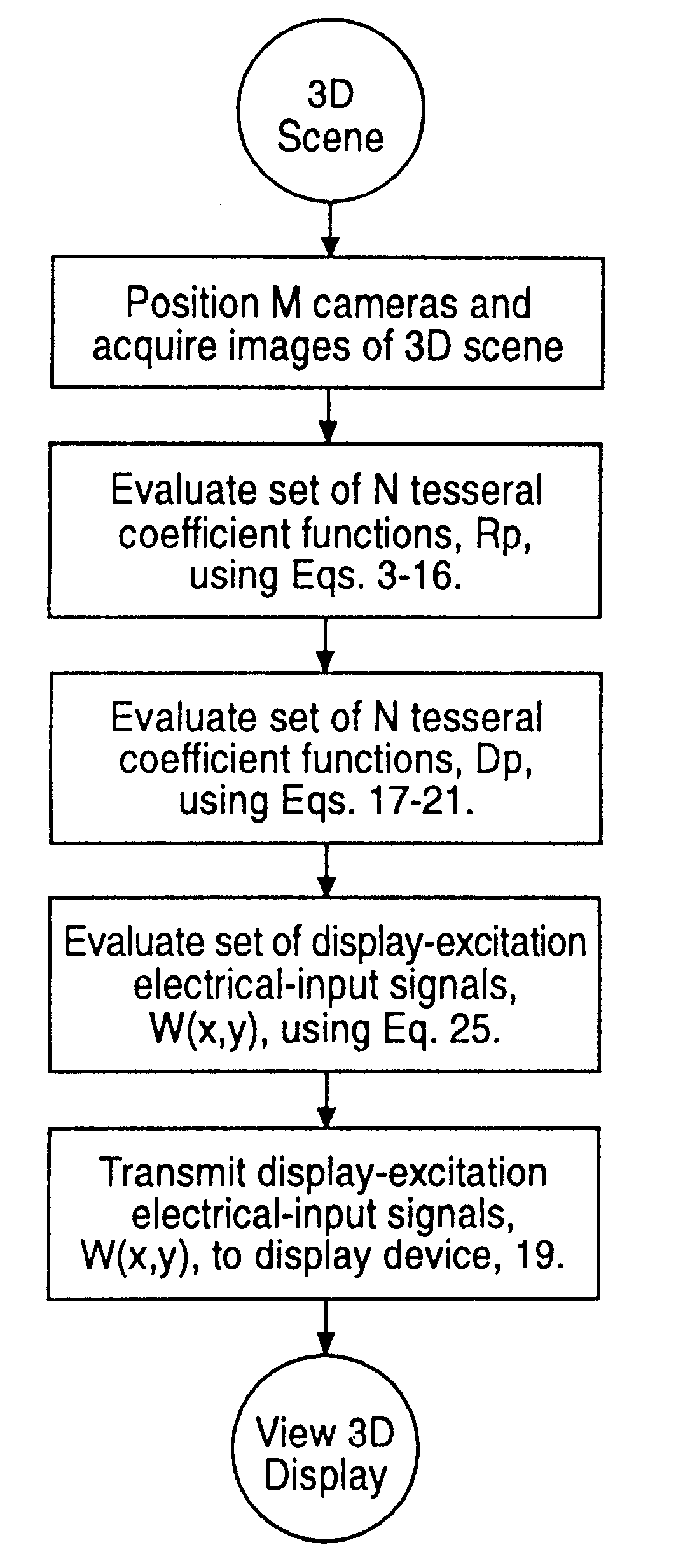
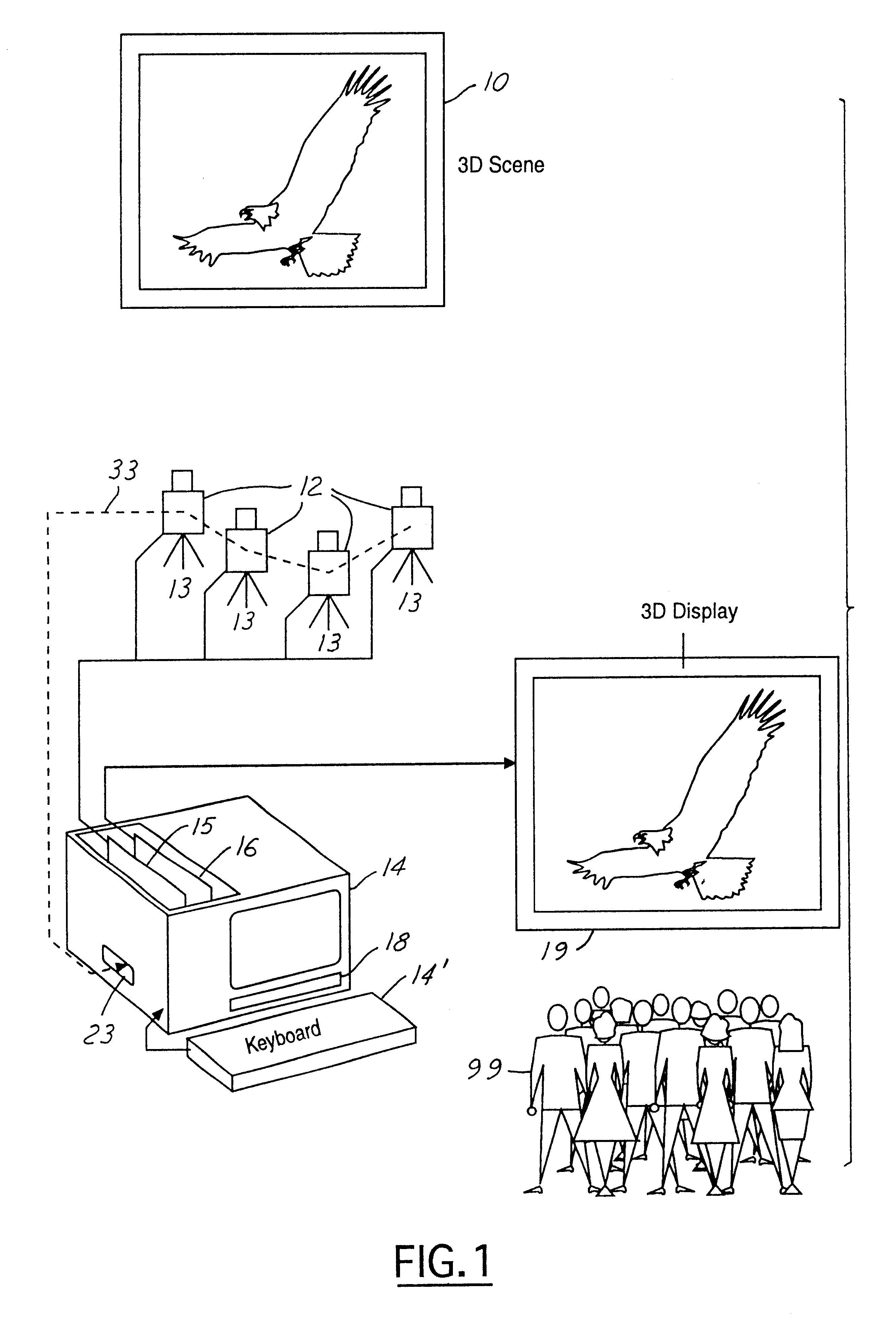
The set of values for the display-excitation electrical-input signals, W.sub.q (x.sub.i,y.sub.j), q=1,2,3,4, i=1, . . . ,480, and j=1, . . . , 512, are evaluated and transferred from computer memory to digital input / output card (15) for transmission to reflected light device (19). The planar display device (19), upon input of the set of display-excitation electrical-input signals, produces a displayed image similar to that seen when viewing the original three-dimensional scene (10), whereby achieving the indicated objectives. It should be further understood that the displayed three-dimensional image may be viewed by observers (99) from a continuum of locations in front of the three-dimensional display, thus enabling full multiviewpoint as well as autostereoscopic capabilities.
It should therefore be understood that the present invention may be embodied in a variety of ways, with the currently preferred embodiment including parallel stigmatic cameras 12, as shown in FIG. 1. An alternative embodiment utilizes tilted stigmatic cameras, as shown in FIG. 21, where each camera 12 is mounted on a gimbal 40 having two degrees of freedom. The gimbal allows for convenient positioning of its attached camera. Yet another embodiment of the invention utilizes parallel astigmatic cameras 12', as shown in FIG. 22. A further embodiment utilizes tilted astigmatic cameras, as shown in FIG. 23, where each astigmatic camera 12' is mounted on a gimbal 40.
It will be additionally understood that the video cameras shown in FIG. 1, FIG. 21, FIG. 22, and FIG. 23 can in the preferred and alternative embodiments of the present invention be adapted for control and communication of their respective spatial positions and optical settings to the processing computer (indicated by the dashed lines 33 in the respective figures connected to the cameras and serial port 23 of computer 14), thus enabling the use of practical and modern television production techniques. It should also be understood that knowledge of the positions and optical settings of all the cameras used in all of the presently preferred embodiments must be available for solving Eq. 3 or Eq. 31 for the display-excitation electrical-input signals.

Problems solved by technology

Because of the inherent mathematical and practical complexities in the three-dimensional imaging problem, as well as the ad hoc nature of previous approaches, the degree of success thus far has been rather limited.
As of yet, there is not a practical system which may be considered to offer all of the capabilities necessary to achieve widespread success.
This has led to the production of relatively poor three-dimensional display systems.

Method used


Image

  • Three-dimensional display system: apparatus and method
  • Three-dimensional display system: apparatus and method
  • Three-dimensional display system: apparatus and method

Examples


Embodiment Construction

specifically for this application. In one alternative embodiment, the functions R.sub.p (i,j), p=1, . . . , N, for each pixel i,j, as given for example in Eq. 11, are assumed to be known. Then, any planar view, m, of the original 3D scene can be reconstructed using the "forward solution," as given by Eq. 11, repeated here: ##EQU34##

In this equation, L.sub.m, is one pixel of the particular planar view (i.e., the m.sup.th view) desired of the 3D scene, while G.sub.mp represents a set of functions which are independent of the original 3D scene itself and thus can be computed a priori. The G.sub.mp are given by Eqs. 12-14, and include the specific position from which it is desired to view the 3D scene. Eq. 11 must be repeated for each pixel i,j, of the desired view. In a presently preferred embodiment, i=1, . . . ,480, and j=1, . . . , 512. Thus it should be understood that the entire 3D scene, i.e., the entire set of graphical information of the original scene, is represented by the se...


PUM


Abstract

In a presently preferred embodiment of the invention, a three-dimensional scene is reproduced on a specialized light display which offers full multiviewpoint capability and auto-stereoscopic views. The displayed image is produced using a set of M two-dimensional images of the scene collected at a set of distinct spatial locations. These M two-dimensional images are processed through a specialized mathematical encoding scheme to obtain a set of NxK display-excitation electrical-input signals, where K is the number of pixels in the display, and N<=M is the number of individual light-radiating elements within one pixel. The display is thus comprised of a total of NxK light-radiating elements. Each of the K pixels is adapted for control of their associated radiance patterns. The display is connected for response to the set of NxK display-excitation electrical-input signals. In this manner, the display provides a multiviewpoint and autostereoscopic three-dimensional image associated with the original three-dimensional scene. An alternative embodiment of the invention is utilized to provide efficient storage and display of 3D computer graphics images.

Description

The invention pertains to apparatus and method for three-dimensional display of three-dimensional objects and scenes.In recent years, various attempts have been made to create three-dimensional displays for various applications, particularly three-dimensional television. Because of the inherent mathematical and practical complexities in the three-dimensional imaging problem, as well as the ad hoc nature of previous approaches, the degree of success thus far has been rather limited.Most developments in three-dimensional display systems have been primarily in stereoscopic techniques, and incorporating a set of discrete multiviews of the three dimensional scenes. These have included both binocular parallax and autostereoscopic three-dimensional systems. Stereoscopic techniques typically require the observer to use a viewing device. In contrast autostereoscopic techniques, which include for example, holographic, lenticular screens and parallax barriers, produce three-dimensional appeara...

Claims


Application Information

Patent Timeline
Patent Type & Authority Patents(United States)
IPC IPC(8): G06T15/10H04N13/00
CPCG06T15/10H04N13/0427H04N13/365
Inventor CHIABRERA, ALESSANDROBIANCO, BRUNOKAUFMAN, JONATHAN J.
Owner TAMIRAS PER PTE LTD LLC
Learn More