
Synchronization of two communication networks of an electronic data-processing system

a technology of electronic data processing and communication network, applied in the direction of data switching network, digital transmission, electrical apparatus, etc., can solve the problem of time delay in the transmission of data from the first, and achieve the effect of extremely small time delay of synchronization messages on the two communication networks

Active Publication Date: 2010-08-05
ROBERT BOSCH GMBH
View PDF8 Cites 0 Cited by
  • Summary
  • Abstract
  • Description
  • Claims
  • Application Information

AI Technical Summary

Benefits of technology

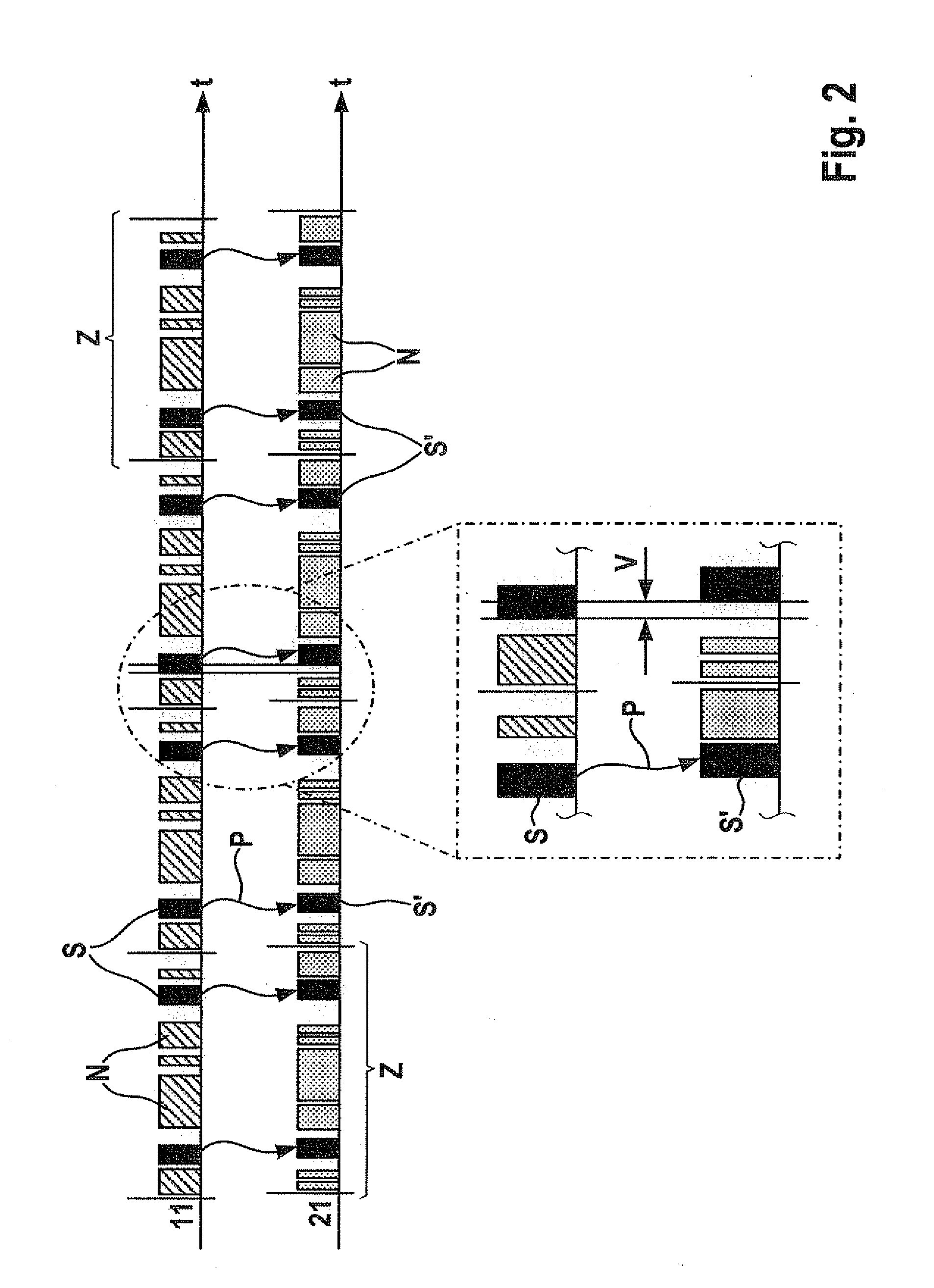
The present invention provides a method and system for synchronizing two communication networks in an electronic data-processing system. This is achieved by establishing time slots for synchronization messages on both networks and generating the synchronization message on the second network based on the first network's synchronization message. This ensures that the same synchronization message is present on both networks, allowing for seamless synchronization between control units. The invention has the advantage of minimizing the time delay of synchronization messages and can be implemented as a computer program on an electronic computing element. Additionally, the invention can involve a switch or a generator to ensure the synchronization message is transmitted and received without interruption.

Problems solved by technology

This conversion and buffer storage lead to time delays in the transmission of the data from the first communication network to the second communication network.

Method used


Image

  • Synchronization of two communication networks of an electronic data-processing system
  • Synchronization of two communication networks of an electronic data-processing system
  • Synchronization of two communication networks of an electronic data-processing system

Examples


Embodiment Construction

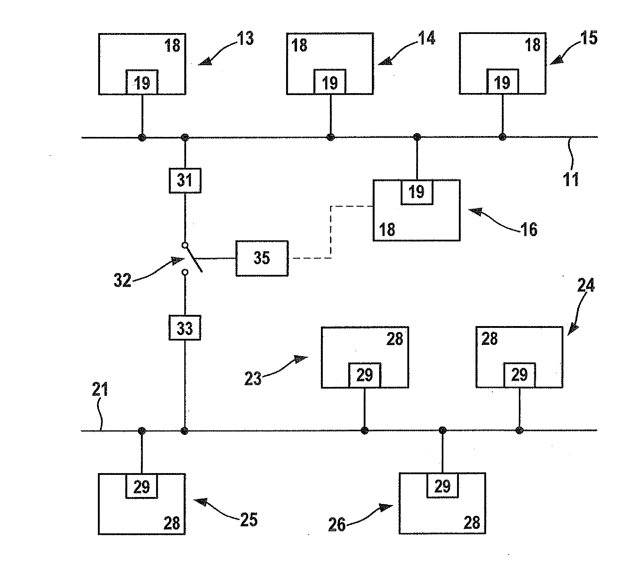
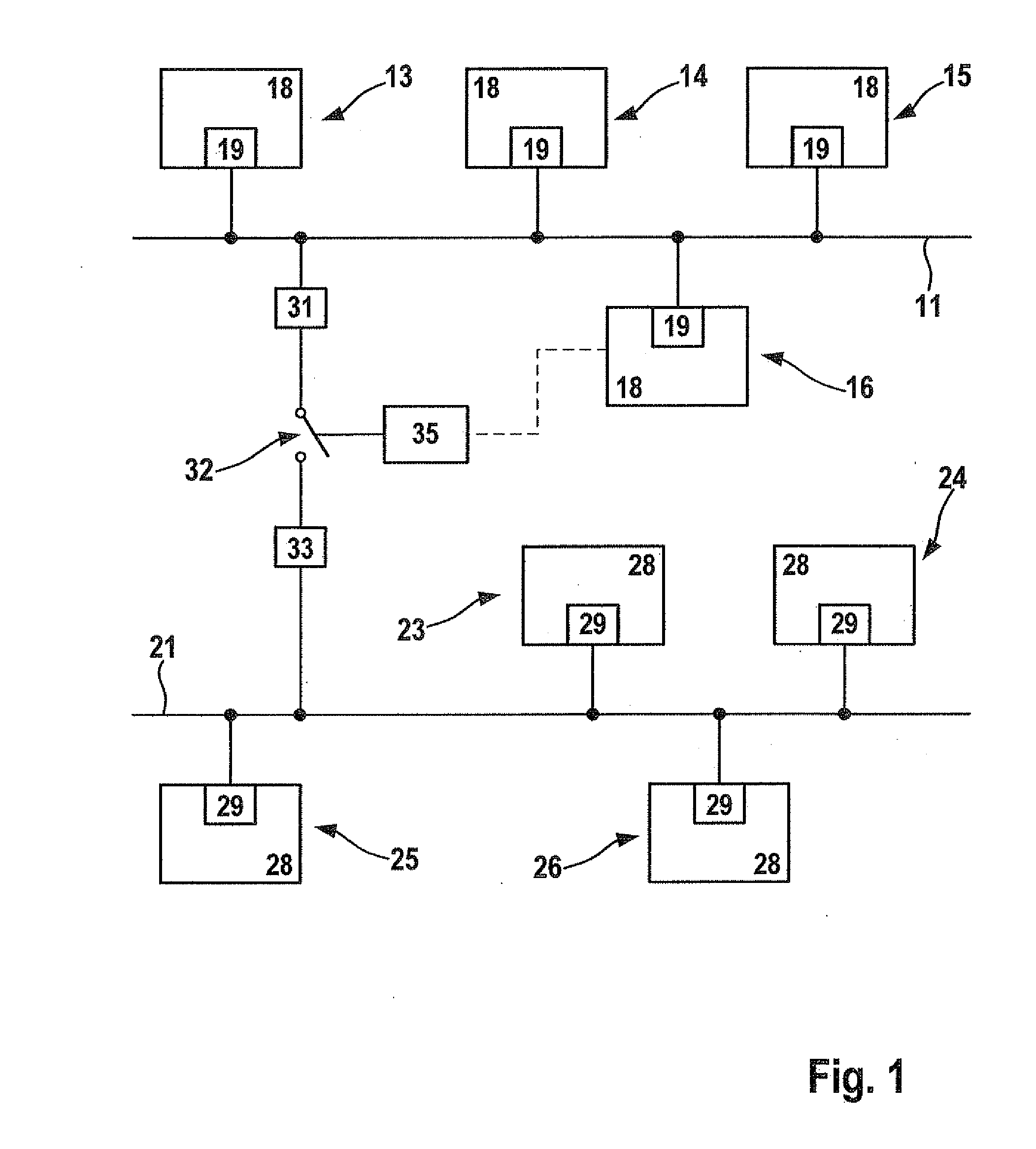
[0016]FIG. 1 shows a first bus 11 of an electronic data-processing system, which may include any type of time-driven communication network. For example, bus 11 may be realized as what is referred to as a FlexRay bus or what is called a TTCAN (Time Triggered CAN)-bus. Bus 11 is provided to transmit digital data, particularly in a motor vehicle.

[0017]By way of example, four nodes 13, 14, 15, 16 are linked to bus 11. For instance, a node may be a component of a control unit, the control unit being able to perform one or more functions, e.g., functions with respect to the injection of fuel into an internal combustion engine, or steering or braking functions of a motor vehicle.

[0018]Each of nodes 13, 14, 15, 16 has a communication controller 18 and a bus transceiver 19. Bus transceiver 19 produces the direct connection of the associated node to bus 11 by writing electrical signals, which represent the digital data to be transmitted, onto bus 11. Communication controller 18 implements a p...


PUM


Abstract

A method for synchronizing two communication networks of an electronic data-processing system, each of the networks including one or more respective nodes, may include establishing for each of the networks a respective time schedule that establishes at least one respective time slot for a respective synchronization message. The synchronization message time slots are established to coincide. The synchronization message of the first communication network is generated by one of the nodes of the first communication network. The synchronization message of the second communication network is generated as a function of the synchronization message of the first communication network.

Description

FIELD OF THE INVENTION[0001]The present invention relates to a method for synchronizing two communication networks, as well as an electronic data-processing system including two communication networks.BACKGROUND INFORMATION[0002]In the case of an electronic data-processing system provided in a motor vehicle, a plurality of control units are interconnected via one or more communication networks. For instance, the communication networks may have bus-like or star-shaped configurations. The control units are used to perform specific functions, e.g., fuel-injection or steering or braking functions of the motor vehicle.[0003]For example, if two so-called event-driven communication networks are present, it is known to connect these communication networks to each other with the aid of what is commonly referred to as a gateway. The gateway has the task of converting and, if necessary, temporarily storing transmitted data, for instance, after an “interrupt” on the first communication network,...

Claims


Application Information

Patent Timeline
Patent Type & Authority Applications(United States)
IPC IPC(8): H04J3/06
CPCH04J3/0655H04L2012/40241H04L12/4625H04L12/4035
Inventor SCHIRMER, JUERGENROHATSCHEK, ANDREAS-JUERGENWEILER, HARALDSCHROFF, CLEMENSHOGENMUELLER, THOMAS
Owner ROBERT BOSCH GMBH
Learn More