AI technical title is built by Patsnap AI team. It summarizes the technical point description of the patent document.
a technology for industrial inspection and led light sources, applied in the field of lighting technology, can solve the problems of poor illuminating effect and inefficiency, inconvenient redesigning of circuit boards, and high system costs, and achieve the effects of simple design transplant, easy conversion, and rapid implementation of product design
Active Publication Date: 2021-02-09
SUZHOU JISHI ELECTRONICS TECH
View PDF17 Cites 0 Cited by
Summary
Abstract
Description
Claims
Application Information
AI Technical Summary
This helps you quickly interpret patents by identifying the three key elements:
Problems solved by technology
Method used
Benefits of technology
Benefits of technology
[0036](1) By adopting the LED modules with modular design, the combination is easy, the transplant of the design is convenient, and for light sources of different sizes or shapes, it is only necessary to rearrange the layout and positions of the LED modules, avoiding the needs of redesigning of PCB board for bearing a plurality of LEDs, in which way the product design could be implemented quickly;(2) The illumination angle is easy to be adjusted, the lighting efficiency is high, the lighting intensity is more uniform, and designing the layout of each bearing surface of the bearing structure according to the preset illumination effects of the light source not only optimizes the illuminating effects, but also increases the use efficiency of light.(3) The time delay of flash synchronization is small, the LED modules are connected in series, and utilizing constant current driving integrated with flash synchronized trigger signals, the synchronizm is high;(4) The drive circuit is arranged in the LED light source, that is, the controller of the light source is integrated into the light source, thereby being able to lower the system costs, reduce the volume, facilitate the use, the external influence on the light emitting of the light source is reduced, and the consistency of the brightness of the light source is good;(5) By adopting external trigger control function, the light source is turned on only if it is required, which not only lowers the power consumption, but also lowers the stimuli of the light source to human eyes, and provides necessary conditions for time-sharing of a plurality of light sources.
Problems solved by technology
Their drawbacks are apparent: (1) The diversity of sizes of light sources brings inconveniences of redesigning of the circuit boards; (2) As regards LED light sources with a certain illumination angle, especially for annular light sources, the inconsistency between the propagation direction of emergent light of LEDs and the propagation direction of emergent light of light sources causes bad illuminating effects and inefficiency.
Moreover, all the existing LED light sources need to be used collectively with an independent light source controller, and one light source controller can drive one or more light sources, resulting in high system costs, large volumes and inconvenience of use; the light source has flash synchronized triggering function, which is achieved by a device outside the light source and the light source controller sending a flash synchronized signal to the light source controller, and the delay of the flash is relatively long.
Method used
Image
Click on the blue label to locate the original text in one second.
Reading with bidirectional positioning of images and text.
Examples
Embodiment Construction
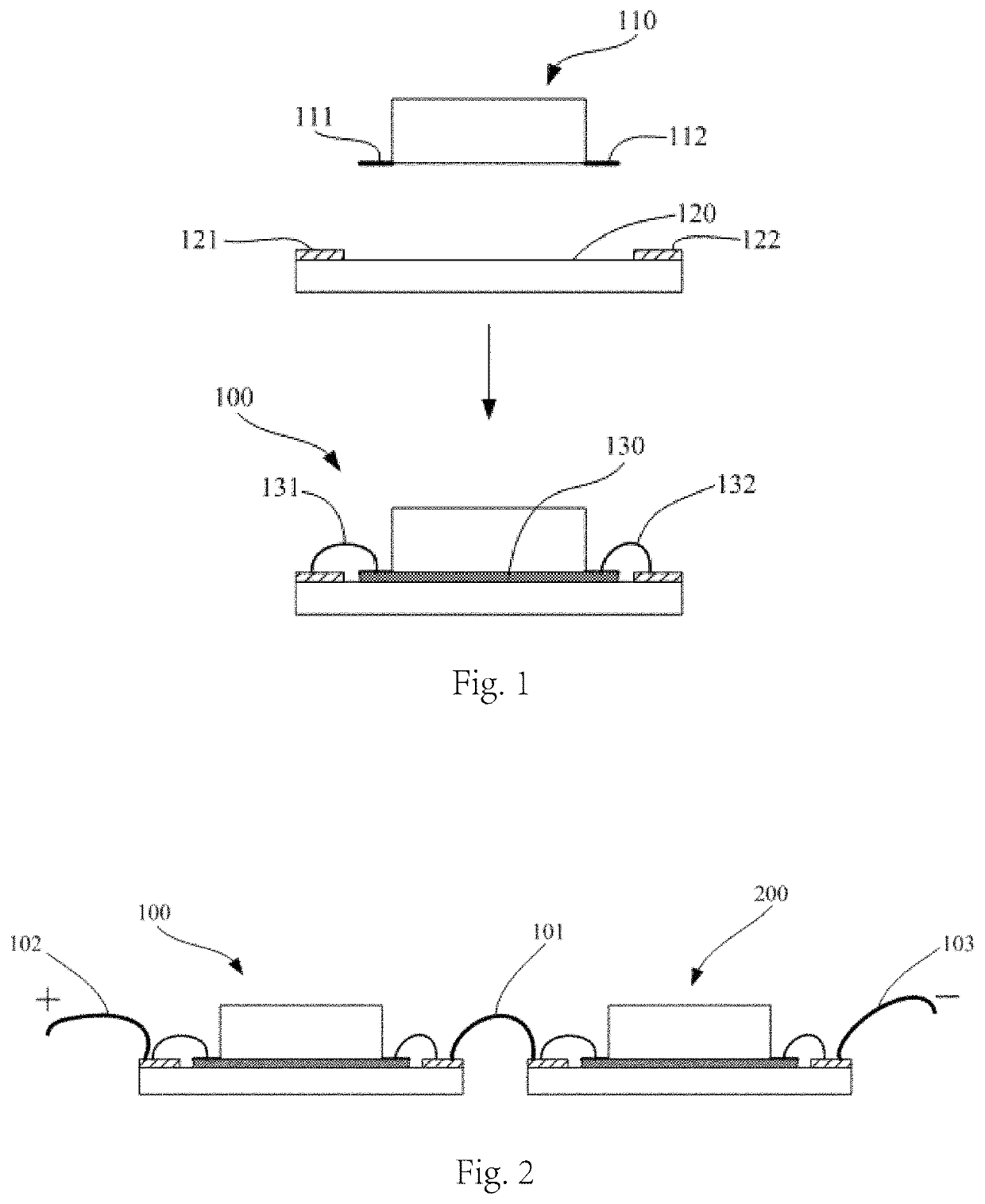
[0048]An LED light source of the present invention uses one or more LED modules, which comprise LEDs and circuit boards, wherein the LEDs are fixed to the circuit boards, and the pins of said LEDs are electrically connected to the electrodes. FIG. 1 shows an example of the manufacturing method of LED modules 100.
[0049]As shown in FIG. 1, by applying a layer of adhesive 130 on the bottom surface of the LED 110 and / or the upper surface of the circuit board 120, the LED 110 is bonded to the circuit board 120, two pins 111, 112 of the LED 110 are electrically connected through conductors 131, 132 to two electrodes 121, 122 of the circuit board 120, respectively, and the production of the LED module 100 is finished. Wherein, the LEDs could be any commercially available or customized LED emitter or COB; additionally, although the LED 110 shown in the figure is surface-mounted type, an in-line type is also adoptable, it is only necessary to design a circuit board matched with it, for examp...
PUM
Property
Measurement
Unit
DC voltage
aaaaa
aaaaa
width
aaaaa
aaaaa
length
aaaaa
aaaaa
Abstract
An LED light source, comprising one or more LED modules (100-800), wherein each of the LED modules (100-800) comprises an LED (110) and a circuit board (120), the LED (110) being fixed to the circuit board (120), electrodes (121, 122) being arranged on the circuit board (120), and pins of the LED (110) being electrically connected to electrodes (121, 122); the LED light source also comprises a bearing structure (10), wherein the bearing structure (10) is provided with a plurality of bearing surfaces (13, 14, 23, 24, 33, 34) for bearing the LED modules (100-800), and various bearing surfaces (13, 14, 23, 24, 33, 34) are arranged such that the normal directions of at least two bearing surfaces are different; and the LED light source also comprises a drive circuit arranged in an enclosure (1) thereof, wherein various LEDs (D3-D10) are connected in series between a current output end and a current input end of the drive circuit. By adopting the LED modules (100-800) with a modular design and the bearing structure (10) having bearing surfaces (13, 14, 23, 24, 33, 34), a plurality of LED modules (100-800) are combined easily, the design and transplantation are convenient, and the illumination angle is adjusted easily, the lighting efficiency is high, and the lighting intensity is more uniform. In addition, the drive circuit is arranged in the LED light source, thereby being able to reduce system costs, reduce the volume, facilitate the use, and reduce the external influence.
Description
CROSS REFERENCE TO RELATED APPLICATION[0001]This application claims priority from PCT / CN2015 / 084934 filed Jul. 23, 2015 which claims priority from Chinese patent application number 201410352611.2 filed Jul. 23, 2014.FIELD OF THE INVENTION[0002]The present invention relates to lighting technology, more particularly, to an LED light source for industrial inspection.DESCRIPTION OF THE PRIOR ART[0003]LED (Light-Emitting Diode) is a kind of semiconductor electronic elements that can convert electric energy into optical energy, and at the present time, commercially available LEDs are packaged granules, comprising two major categories: emitter and COB (Chip on Board), the core structures thereof are both LED wafers, that is, PN junctions. LED emitters and COB also comprise substrates for bearing LED wafers, on which there are pins for electric connection with the outside. LED emitters and COB can also comprise fluorescent materials for changing the colors of the emergent light, lens for gu...
Claims
Application Information
Patent Timeline
Application Date:The date an application was filed.
Publication Date:The date a patent or application was officially published.
First Publication Date:The earliest publication date of a patent with the same application number.
Issue Date:Publication date of the patent grant document.
PCT Entry Date:The Entry date of PCT National Phase.
Estimated Expiry Date:The statutory expiry date of a patent right according to the Patent Law, and it is the longest term of protection that the patent right can achieve without the termination of the patent right due to other reasons(Term extension factor has been taken into account ).
Invalid Date:Actual expiry date is based on effective date or publication date of legal transaction data of invalid patent.

