LED light source for industrial inspection

a technology for industrial inspection and led light sources, applied in the field of lighting technology, can solve the problems of poor illuminating effect and inefficiency, high system cost, and inconvenient redesign of circuit boards

Active Publication Date: 2017-07-27
SUZHOU JISHI ELECTRONICS TECH
View PDF3 Cites 3 Cited by
  • Summary
  • Abstract
  • Description
  • Claims
  • Application Information

AI Technical Summary

Benefits of technology

[0035]For a more complete understanding of the purposes, features and effects of the present invention, the conceptions, specific structu

Problems solved by technology

Their drawbacks are apparent: (1) The diversity of sizes of light sources brings inconveniences of redesigning of the circuit boards; (2) As regards LED light sources with a certain illumination angle, especially for annular light sources, the inconsistency between the propagation direction of emergent light of LEDs and the propagation direction of emergent light of light sources causes bad illuminating effects and inefficiency.
Moreover, all the existing LED light sources

Method used


Image

  • LED light source for industrial inspection
  • LED light source for industrial inspection
  • LED light source for industrial inspection

Examples


Embodiment Construction

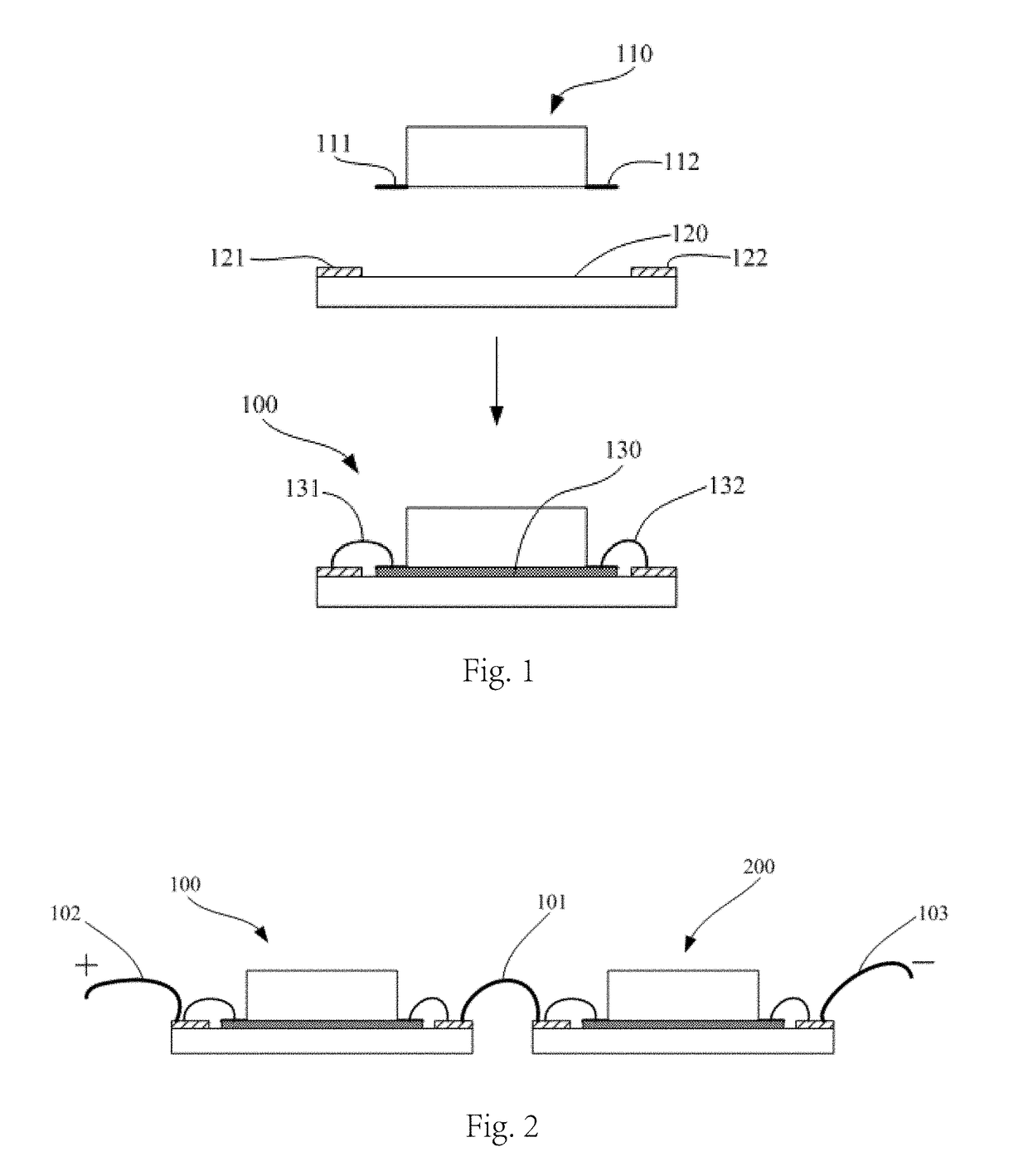
[0046]An LED light source of the present invention uses one or more LED modules, which comprise LEDs and circuit boards, wherein the LEDs are fixed to the circuit boards, and the pins of said LEDs are electrically connected to the electrodes. FIG. 1 shows an example of the manufacturing method of LED modules 100.

[0047]As shown in FIG. 1, by applying a layer of adhesive 130 on the bottom surface of the LED 110 and / or the upper surface of the circuit board 120, the LED 110 is bonded to the circuit board 120, two pins 111, 112 of the LED 110 are electrically connected through conductors 131, 132 to two electrodes 121, 122 of the circuit board 120, respectively, and the production of the LED module 100 is finished. Wherein, the LEDs could be any commercially available or customized LED emitter or COB; additionally, although the LED 110 shown in the figure is surface-mounted type, an in-line type is also adoptable, it is only necessary to design a circuit board matched with it, for examp...


PUM


Abstract

An LED light source, comprising one or more LED modules (100-800), wherein each of the LED modules (100-800) comprises an LED (110) and a circuit board (120), the LED (110) being fixed to the circuit board (120), electrodes (121, 122) being arranged on the circuit board (120), and pins of the LED (110) being electrically connected to electrodes (121, 122); the LED light source also comprises a bearing structure (10), wherein the bearing structure (10) is provided with a plurality of bearing surfaces (13, 14, 23, 24, 33, 34) for bearing the LED modules (100-800), and various bearing surfaces (13, 14, 23, 24, 33, 34) are arranged such that the normal directions of at least two bearing surfaces are different; and the LED light source also comprises a drive circuit arranged in an enclosure (1) thereof, wherein various LEDs (D3-D10) are connected in series between a current output end and a current input end of the drive circuit. By adopting the LED modules (100-800) with a modular design and the bearing structure (10) having bearing surfaces (13, 14, 23, 24, 33, 34), a plurality of LED modules (100-800) are combined easily, the design and transplantation are convenient, and the illumination angle is adjusted easily, the lighting efficiency is high, and the lighting intensity is more uniform. In addition, the drive circuit is arranged in the LED light source, thereby being able to reduce system costs, reduce the volume, facilitate the use, and reduce the external influence.

Description

FIELD OF THE INVENTION[0001]The present invention relates to lighting technology, more particularly, to an LED light source for industrial inspection.DESCRIPTION OF THE PRIOR ART[0002]LED (Light-Emitting Diode) is a kind of semiconductor electronic elements that can convert electric energy into optical energy, and at the present time, commercially available LEDs are packaged granules, comprising two major categories: emitter and COB (Chip on Board), the core structures thereof are both LED wafers, that is, PN junctions. LED emitters and COB also comprise substrates for bearing LED wafers, on which there are pins for electric connection with the outside. LED emitters and COB can also comprise fluorescent materials for changing the colors of the emergent light, lens for guiding the emergent light and structures for heat sinking; usually, lens allows the propagation direction of the emergent light of LEDs to be perpendicular to the substrates in the LEDs.[0003]LEDs have a wide range of...

Claims


Application Information

Patent Timeline
IPC IPC(8): G03B15/05F21V23/06G01N21/88F21V15/01H05B33/08F21V19/00F21V23/00H05B44/00
CPCG03B15/05F21V19/0015F21V23/06F21V23/003F21V15/01G01N2201/0621G01N21/8806F21Y2115/10F21Y2105/18F21Y2105/16H05B33/0824G03B2215/0567H05B45/44
Inventor LIU, YONG
Owner SUZHOU JISHI ELECTRONICS TECH
Why Eureka
Try Eureka