
Audio system with varying time delay and method for processing audio signals

a technology of audio signal and time delay, which is applied in the field of audio system with varying time delay and method for processing audio signals, can solve the problems of severely restricting the processing capabilities of a given audio system, poor sound quality, and the range of disturbing effects experienced by users, and achieves high background noise level, large throughput, and high demands on the anti-feedback system

Active Publication Date: 2007-07-26
OTICON
View PDF5 Cites 3 Cited by
  • Summary
  • Abstract
  • Description
  • Claims
  • Application Information

AI Technical Summary

Benefits of technology

[0012] Hence, a hearing aid system which makes use of the method according to the invention can vary the delay in steps (or continuously) in addition to the well known variations such as fast anti-feedback and slow anti-feedback, detection of speech or absence of speech, etc. A short delay may for instance be desirable when a high speech to noise ratio is present, whereas a long delay may be useful for the hearing impaired in situations where a high background noise level is present and where noise reduction oriented processing is imperative. A long delay could also be desirable in cases where the demands on the anti-feedback system are unusually high, since a large throughput delay makes it possible to increase the performance of the anti-feedback system. When the invention is used in connection with a hearing aid system the left and right hearing aids should have their delays synchronized by means of a communication link between the hearing aids.
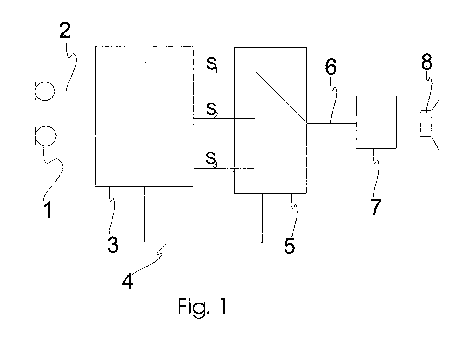
[0013] In an embodiment of the invention the input signal is initially analysed and based on results thereof a choice is made as to which algorithm and accompanying time delay should be performed in order to provide the most rewarding output signal for the user, whereby an according decision signal from an analyse block is served at the DSP unit in order to realize the chosen algorithm. In this way, when no change of time delay or processing algorithm is being performed, the DSP unit will only perform one of the possible algorithms, and this will aid to save power. This is most important in portable systems like hearing aids and headsets.
[0015] According to an embodiment of the invention a time alignment between a current processed signal and a desired processed signal is provided by introducing a time delay in the processed signal having the smallest time delay of the two whereafter fading from a current signal to a desired signals is performed. In this way it becomes possible to change from the output of algorithms with different time delay without audible side effects.
[0016] In a further embodiment the time delay of the just chosen desired signal is reduced as much as possible. Hereby it is assured that the signal provided for the user always has as small a time delay as possible.

Problems solved by technology

It is well documented that the delay, introduced by digital processing in modern audio systems, can lead to a range of disturbing effects experienced by the user.
While a short delay is desirable in order to limit the disturbing effects experienced by the user, (poor sound quality, difficulty in locating direction of sound source) when a short delay is specified it severely limits the processing capabilities of a given audio system.
Hence, the more advanced processing used in the system, the longer the delay will inevitably be.
One example is noise reduction oriented processing which is often based on block processing, and if the system is only allowed to impose a short delay, only very limited block length can be used leading to poorer performance.
This delay is a compromise between the risk of subjectively experienced problems and the processing capabilities.
Such open instruments may be particularly sensitive to the delay introduced by the audio processing.
In general, increasing the number or quality of the filterbank bands leads to increased delay and power usage.
The US document does not allow the change of processing time to be performed on-line during processing, but solely mentions the possibility to program a certain delay or frequency resolution prior to the use of the audio device.

Method used


Image

  • Audio system with varying time delay and method for processing audio signals
  • Audio system with varying time delay and method for processing audio signals
  • Audio system with varying time delay and method for processing audio signals

Examples


Embodiment Construction

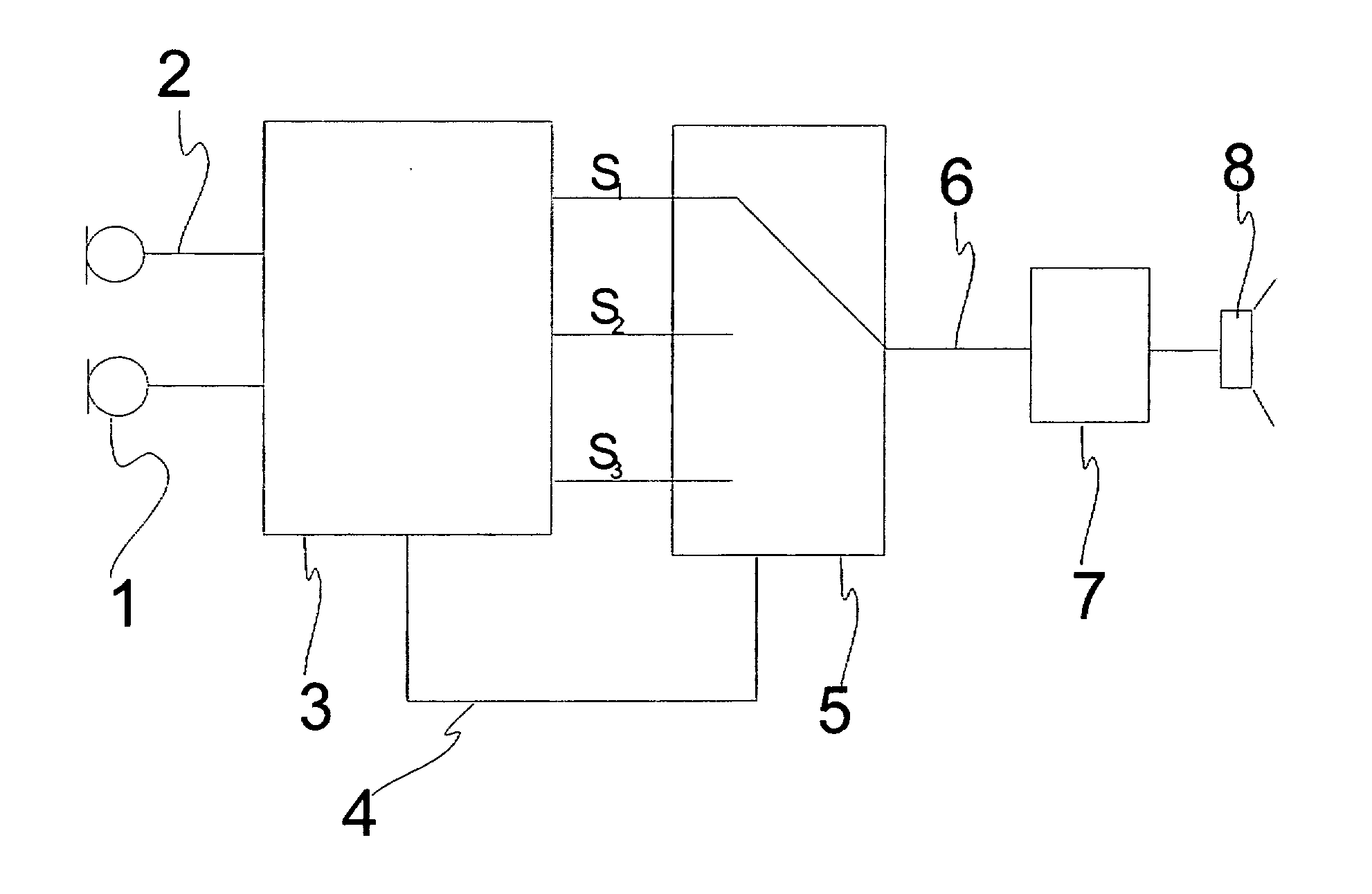
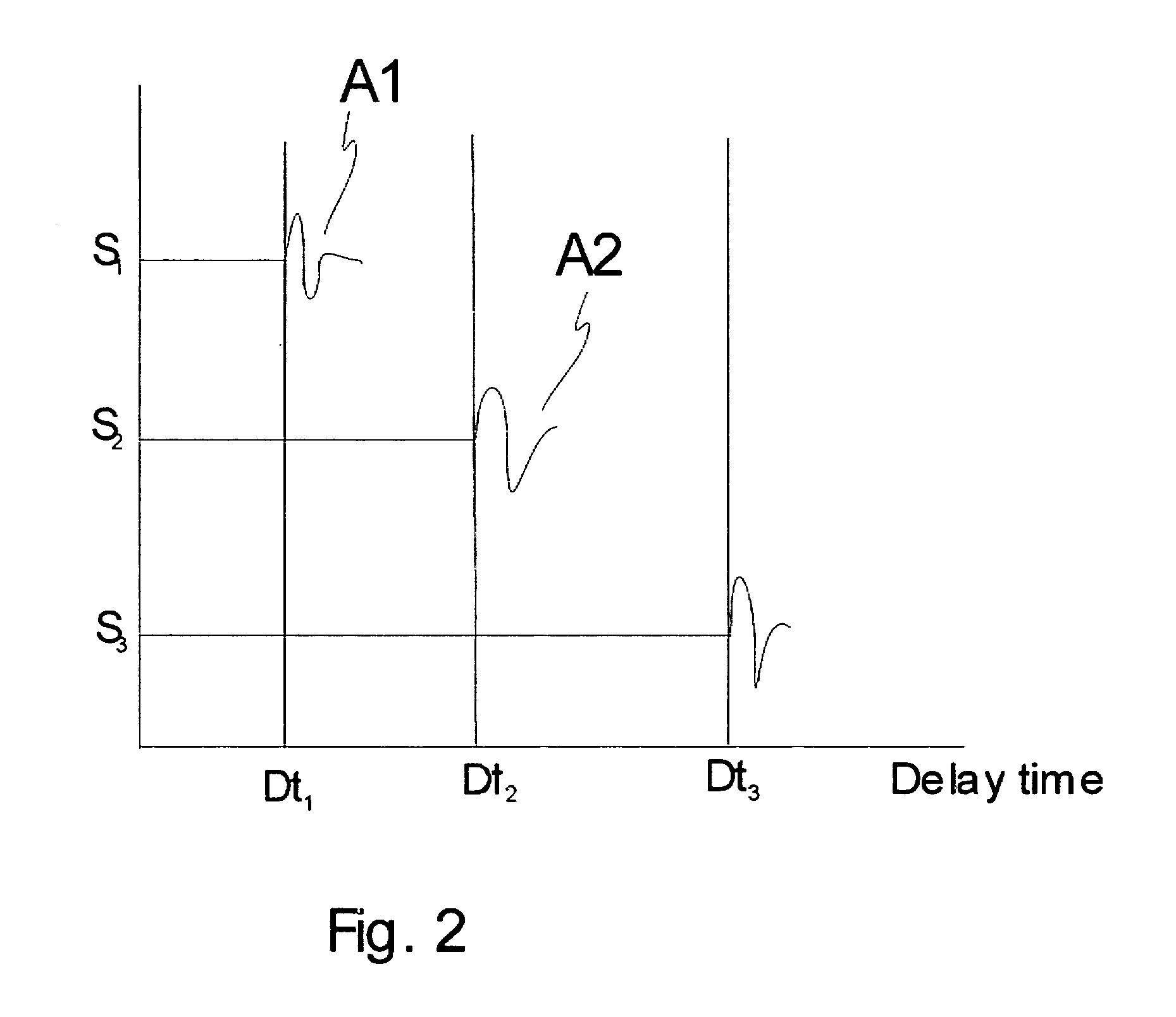
[0021]FIG. 1 illustrates a simplified example of a hearing aid which embodies an example of the method according to the invention. A diagram of the signal path in a hearing aid is shown, whereby one or more microphones 1 are arranged to pick up environmental sounds. In the hearing aid other sound signals may be transmitted through the signal path, such as telecoil signals or other wireless or wired audio signal as well known in conventional hearing aids. The incoming signals 2 are digitized in the usual way (not shown in the figure) and routed to a digital signal processing unit (DSP) 3. Here a usual amplification and noise damping process is performed on the incoming signal as is usual in hearing aids. The method according to the invention allows two or more different algorithms to be performed on the audio signal in the DSP unit and thus delivering two or more output signals, illustrated in FIG. 1 by S1, S2 and S3. The algorithms have each their time delay Dt1, Dt2 and Dt3 as disp...


PUM


Abstract

The invention regards a method for processing audio signals whereby an audio signal is captured, digitized and processed in the digital domain by a digital signal processing unit or DSP, and where a processed output signal from the digital signal processing unit is converted to the analog domain and served at a transducer for providing a sensation of sound. The DSP unit is provided with mean for performing at least two different digital algorithms which delivers each their processed signal having each their non identical time delay and further the most rewarding sound signal is chosen and served at the output transducer.

Description

AREA OF THE INVENTION [0001] The invention regards audio systems as used in hearing aids, headsets and other devices wherein an environmental audio signal is processed and continually served at one or more listeners. BACKGROUND OF THE INVENTION [0002] It is well documented that the delay, introduced by digital processing in modern audio systems, can lead to a range of disturbing effects experienced by the user. The processing delay should in general be lower than 10 milliseconds. This time is based on average ratings and rather large deviations exist depending on degree of: amplification, incoming sound signal, type of sound processing and individual differences between people. The range of acceptable values may be roughly 3 to 40 milliseconds depending on such factors. [0003] While a short delay is desirable in order to limit the disturbing effects experienced by the user, (poor sound quality, difficulty in locating direction of sound source) when a short delay is specified it seve...

Claims


Application Information

Patent Timeline
Patent Type & Authority Applications(United States)
IPC IPC(8): G06F17/00G10L21/02
CPCG10L21/02
Inventor RASMUSSEN, KARSTEN
Owner OTICON
Learn More